Importing large survey data
This document outlines a workflow for working with large point files to create surfaces when only a smaller subset of data is necessary. The steps mentioned leverage Civil 3D options to optimize performance by minimizing data load as early as possible in the workflow.
The best approach for managing large datasets is to reduce data volume before importing, for instance, by defining an import boundary. This allows Civil 3D to only import relevant data within that boundary, enhancing efficiency from the start. Later methods, such as hiding portions of the surface outside a boundary, require Civil 3D to handle the full dataset initially, which can already strain performance. Similarly, allowing Civil 3D to remove excess points can also lead to performance issues.
For areas with minimal elevation variation, external tools may be more efficient for removing unnecessary points than Civil 3D. Recommended tools for this purpose include ReCap and 3ds Max. If you conduct your own drone surveys and use AGISOFT for data processing, you can reduce point density directly within that software.
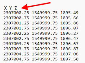
This workflow example uses a text file with point data in XYZ format and a defined coordinate system. It’s important to note that this is one possible approach, and alternative methods may yield similar outcomes.
Workflow
- Open Civil 3D and go to Toolspace.
- On the page “Prospector”, create a new surface and choose a name.
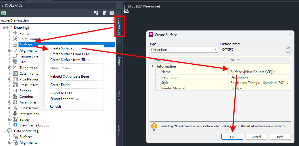
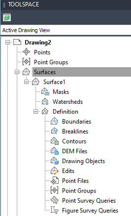
- Open the list of Surfaces and go to the “Definition” section.
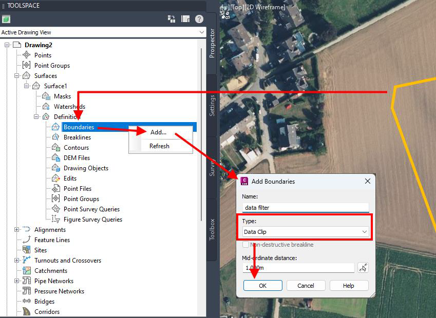
- Add a boundary for the data import.
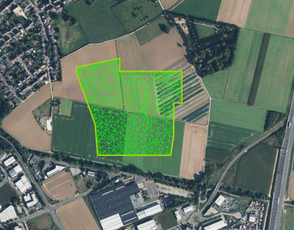
If the measured data of the file covers a larger area than the actual project uses, it is most efficient to just import the points inside the project boundary.
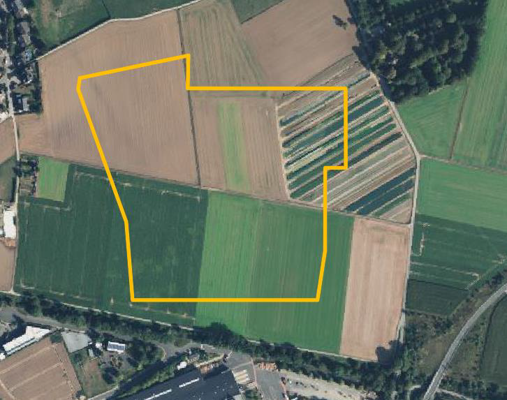
For this step, you need a polyline that excludes all points outside its borders. The below steps can be used to draw a rough line around the project site.
Set the coordinate system that fits the survey data and show the Bing map.
Create a polyline by two points from the XYZ file to zoom to a location close to your project site if no reference object is given. That should bring you close enough to the location, so you can find the actual plant area by comparing roads, buildings or other reference points displayed in Google Earth or Maps.
Create a closed polyline that surrounds the project area in a suitable distance. It won’t be possible to show surface parts outside this border later, as we want to avoid the import of outside points, so don’t get too close to fence lines.
Add the polyline to the surface as Boundary of the type “Data Clip”.
- Check the point file for format issues as headlines that can’t get read into Civil 3D, such as XYZ format headers.
In case you’re not sure about the file validity, Civil 3D will show if the format is invalid for direct import when being selected in the next step. You can come back here in case the file is refused.
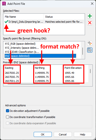
- Add the point file to the surface definition with „+“ . You might need to choose the proper filed format or “All files” in the selection dialogue.
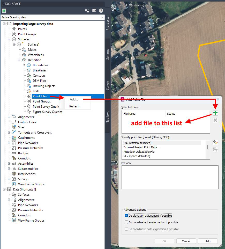
- Set the format and check it matches before you press <OK>.
If the file is rejected, no green hook appears. In that case, go back to check dhe point file.
You need to take care the columns don’t get mixed up.
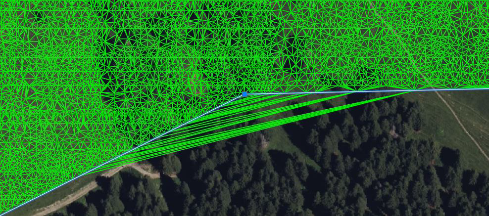
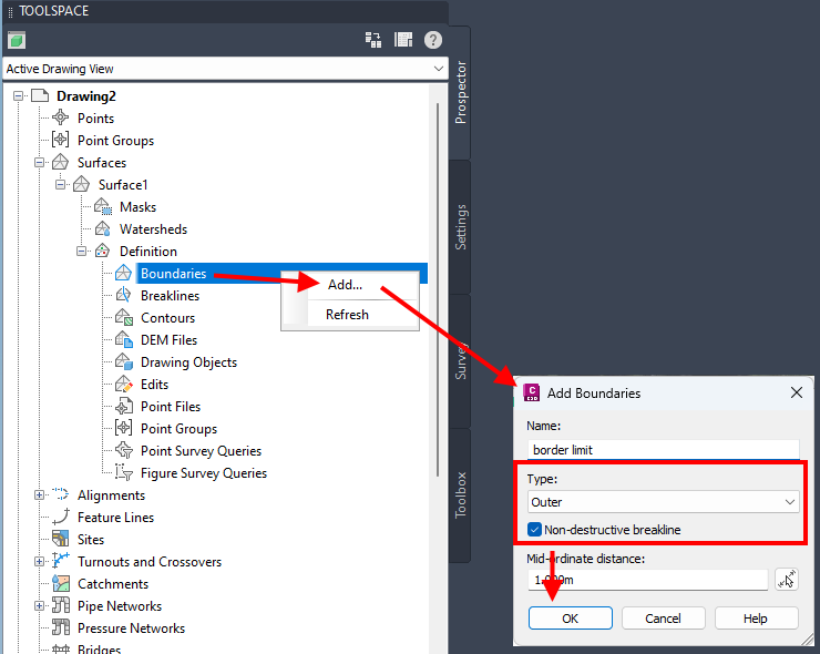
- The resulting surface just uses the points inside the border, but it still shows triangles outside it for convex borders.
It is possible to add the limiting polyline a second time as boundary of the type “Outer”, which will cut away the above triangles. The checkbox “Non-destructive breakline” should be activated before you continue.
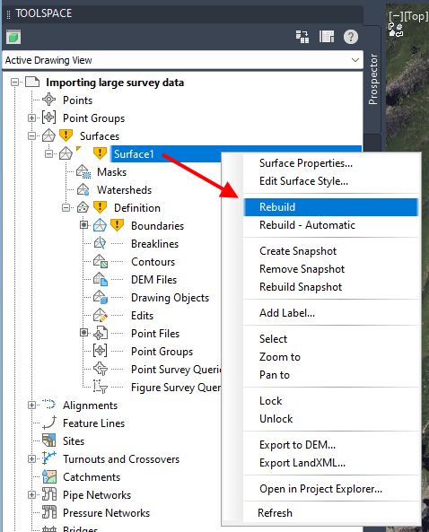
- In case the Toolspace still shows issues with the surface, you need to rebuild it manually.
The resulting surface is ready to be used with Helios 3D. If it doesn’t appear to the list on the page “Placement”, it requires a manual refresh.
Unlinking the point file from the DWG file
However, the point cloud with the large amounts of data is currently still linked to the drawing. If the terrain model finally meets your requirements, possibly also after a “simplification”, you can reduce or disconnect this amount of data with the following steps.
| After this, it is no longer possible to edit the terrain model again. |
The following steps are necessary:
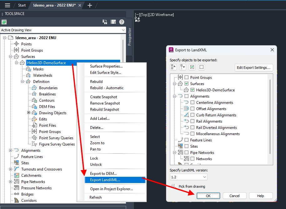
- Create an XML file from the current surface.
- In a real project, put the LandXML file to the same directory you want to save the final DWG file to, as there will be a permanent reference/link.
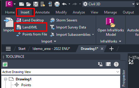
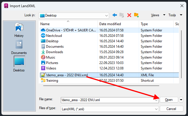
- Open a new drawing and import the LandXML file, as in the following picture guide.
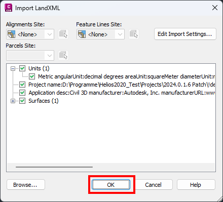
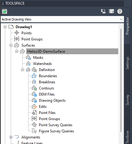
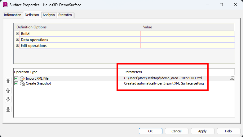
- After the import, you can see that no point file is connected. Please note the information at the end of the last image in this document.
A “snapshot” has been created. The size of the XML file should now be considerably smaller than the original point file(s).
| The referenced LandXML file mustn’t get deleted and it should be permanently reachable. After moving the DWG file, it might be required to set the path in the above dialogue (Surface Properties) again. |