Electric – Ribbon
The first subsection describes the database entries required for the Electric module. Following that, a detailed explanation of the full functionality of the Electric module is provided.
Needed Database Entries
The Electric module requires specific device records in the database, such as grids, cables, transformers, inverters, and combiner boxes. With the exception of grids, these devices can also be created while creating a layout; however, it is recommended to create the records in the component management of the Helios database application.
In the final step of this section, we explain how to create a grid record. Since a grid is not a physical device but rather an abstract one, it must be created in the choice list module.
The procedure for creating devices is the same as for any other component in the component management. Therefore, this section focuses on the data specific to each component type.
In the first version of the Electric module, most of the input fields for electrical devices are not yet used in calculations. However, we recommend entering as much information as possible to avoid the need to update all records whenever the program’s functionality changes.
| At this time, some values are not used internally by the program. |
All inputs that are essential for the device to function will be marked with a red frame. An example of this is the input for the count of any electrical device, as transformers, inverters, or combiner boxes cannot be used without this value.

Other values, such as the conductor material and resistivity of a cable, are optional. If these values are missing, the cable can still be used to calculate the total cable required. However, the loss calculation will not be accurate without these inputs, which is why they are marked with an orange frame.

Values that are optional but contribute to a more accurate yield assessment calculation are marked with a sky-blue frame.

Transformer

Transformers are automatically inserted into device areas based on the assignments in the layout.
The input for count and rated voltage is required to use the transformer. The efficiency value reduces the power on the output cable before the cable loss calculation begins. All other entries are optional.
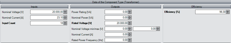
Nominal Voltage [V]
Insert the nominal input voltage (low-voltage side).
Nominal Current [A]
Insert the nominal input current (low-voltage side).
Input Count (required)
Insert the number of inputs.
Power Rating [VA]
Insert the rated power at 25°C (medium-voltage side).
Nominal Power [VA]
Insert the nominal output power at 40°C (medium-voltage side).
Rated Voltage [V] (required)
Insert the rated grid voltage (medium-voltage side).
Nominal Voltage min/max [V]
Insert the nominal AC voltage range (medium-voltage side).
Nominal Current [A]
Insert the nominal output current (medium-voltage side).
Rated Power Frequency [Hz]
Insert the rated power frequency (medium-voltage side).
Efficiency [%]
The efficiency of the device reduces the power delivered to the output cable and decreases the losses in the cable due to its characteristics and length. A value of 0.00% is interpreted as 100%, meaning there is no internal loss.
Inverter

For inverters, most of the input values displayed below are not yet used in Helios 3D. Currently, only the input count is considered. The following values are required:
- Input Count
- Maximum Voltage (Udc MPP)
- Nominal Voltage (Vac nom)
- Euro Efficiency
The other values, marked in bold, will improve the results of the internal yield assessment.
MPPTs can be added to the list below the input fields.
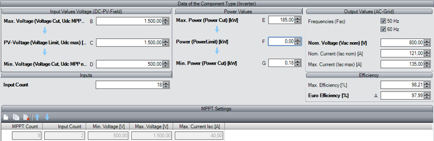
Input Values Voltage (DC-PV-Field)
Max. Voltage (Voltage Cut, Udc MPP max) [V] (required)
Insert the maximum MPP voltage (Voltage Cut). If the voltage exceeds this value, the inverter is disabled for safety reasons (see the following Figure at Voltage Cut min).
This value is considered for the yield assessment if set.
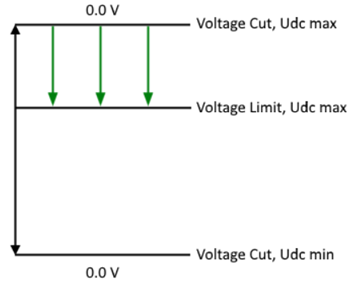
PV Voltage (Voltage Limit, Udc max) [V] (optional)
Insert the maximum PV voltage (Voltage Limit). If the voltage exceeds the Voltage Limit but not the Voltage Cut, the voltage will be reduced to the Limit value (see the previous Figure at Voltage Cut min).
This value is considered for yield assessment if set.
Min. Voltage [V] (required)
Insert the minimum voltage at rated power. Below this value, the device will not be active, meaning strings cannot be connected if the STC string voltage is too low.
Input Count (required)
Insert the number of inputs. Helios uses this value to calculate the number of inverters required. Each input can connect a single module string (for string inverters) or a combiner box (for central inverters). Depending on the placement settings, the device will be inserted behind the last string assigned to it.
Power values
Max. Power (Power Cut) [kW] (required)
Insert the maximum power (Power Cut). If this limit is exceeded, the inverter will be disabled for safety reasons (see the following Figure 165 at Power Cut min).
This value is considered for yield assessment if set.
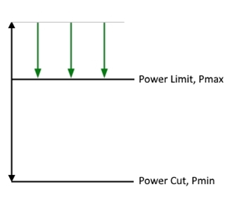
Power (Power Limit) [kW] (optional)
Insert the maximum PV power (Power Limit). If the Power Limit is exceeded but not the Power Cut, the power will be reduced to the Limit value (see the previous Figure at Power Cut min).
This value is considered for the calculation of cable losses and additionally for yield assessment if set.
Min. Power (Power Cut) [kW] (optional)
Insert the minimum power (Power Cut). Below this value, the inverter will not be active.
This value is considered for yield assessment if set.
Output Values (AC-Grid)
Frequencies (Fac) (not used)
Select the possible frequencies.
Nominal Voltage (Uac nom) [V] (required)
Insert the nominal voltage for the inverter output. This value is used in the calculation of cable losses.
Nominal Current (Iac nom) [kW] (not used)
Insert the nominal current for the inverter output.
Max. Current (Iac max) [kW] (not used)
Insert the maximum current for the inverter output.
Efficiency
Max. Efficiency [%] (not used)
Insert the maximum efficiency of the inverter.
European Efficiency [%] (required)
Insert the European efficiency of the inverter. This value is mandatory for the yield assessment!
Combiner Box

For inverters, most input values are still not used in Helios 3D. Currently, only the input count is considered. The required inputs are the input count and the absolute maximum PV voltage (Vdc max).
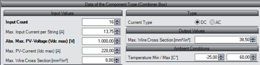
Input Values
Input Count (required)
Insert the number of inputs. Helios uses this value to calculate the number of combiner boxes needed. Depending on the placement settings, the device will be inserted behind the last string assigned to it.
Max. Input Current per String [A] (not used)
Insert the maximum input current per string.
Abs. Max. PV-Voltage (Udc max) [V] (required)
Insert the maximum PV voltage. If this value is set, it will be checked when creating a new string definition.
Max. PV-Current (Idc max) [A] (not used)
Insert the maximum PV current.
Max. Wire Cross Section (not used)
Insert the maximum wire cross section.
Type
Current Type (not used)
Select the current type. A combiner box can be used for either the AC or DC side.
Output Values
Max. Wire Cross Section (not used)
Insert the maximum wire cross section.
Ambient Conditions
Temperature Min. / Max. [C°] (not used)
Insert the minimum and maximum ambient temperature.
Cable

Cables are essential for electrical design and for calculating the total cable lengths per article for material lists. Additionally, losses based on the input power and the length of the cable are calculated.
For AC losses, the impedance value is used when available. In the DC part or if no impedance value is provided, the resistance in Ω/km is used. If the resistance is missing, the conductor material (its resistivity value) and cross-section are used instead. The values in Ω/km have been added starting with program version 2024.
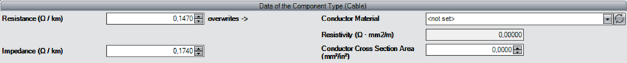
Resistance (Ω/km)
This value is used for calculating power losses due to the cable length in the DC part or in the absence of an impedance value.
Impedance (Ω/km)
This value is used for calculating power losses due to the cable length in the AC part.
Conductor Material (required)
Select the conductor material from the choice lists. The resistivity value of the material is defined there.
Resistivity (Ω * mm²/m) (required)
This shows the resistivity value defined for the conductor material, which is set in the choice lists.
Conductor Cross Section Area (required)
Insert the conductor cross-sectional area. This value is necessary for calculating power losses caused by cable lengths.
Grid

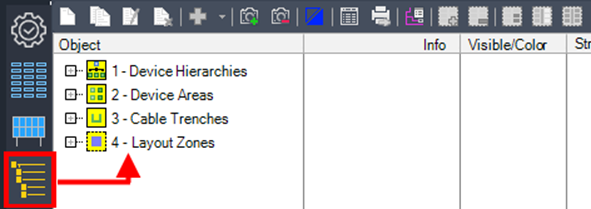
Grids can only be created in the choice list module

of the Helios 3D database application.
In the folder structure, select the entry „Electrical Grid“ as shown in the figure below.
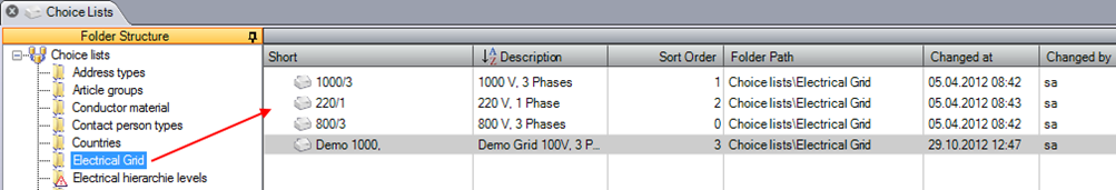
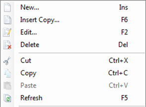
In the list to the right of the folder structure, you can create or edit entries using the „Edit“ buttons or the context menu.
The following figure shows the creation dialog. At this stage, the values for voltage and the number of phases are not yet considered.
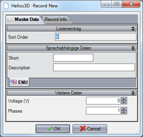
A good example entry might be:
- Short: 1000/3
- Description: 1000 V, 3 Phases
- Voltage: 1000
- Phases: 3
Electric – Definition
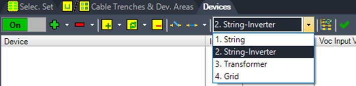
The Electricity tab is divided into two sub-tabs. The first sub-tab is used for defining an electrical layout (see the following figure) and for displaying the results based on predefined categories. The second sub-tab is used for displaying the final electrical structure.
To define a layout, you can walk through the numbered points displayed above. The order of these points follows the steps of the default workflow.
Button Menu
New

Create a new electrical element in the „Structure“ list, based on the selected entry.
Copy

Copy a selected element in the „Structure“ list. A renaming dialog will appear for the copied element, allowing you to assign a new name.
Rename

Rename a selected element in the „Structure“ list. A renaming dialog will appear, allowing you to enter the new name.
Delete

Delete a selected element in the „Structure“ list. The element will be removed from the list permanently.
Parts List

Opens the dialog for creating parts lists, which contain information about any electrical components used in the selected surface, area, or field. These parts lists are similar to those from the placement, and as a result, the data can be found on the „Evaluation“ tab in the Helios 3D palette.
Add to Selection Set

Add a selection of arrays (default) or modules to the selected selection set. To do this, first select a selection set and then click this button. Afterward, you can select one or multiple geometries in the drawing to add to the set.
Remove from Selection Set

Remove a selection of arrays (default) or modules from the selection set. To do this, first select a selection set and then click this button. Afterward, you can select one or multiple geometries in the drawing to delete from the set.
Rest to New Selection Set

All unassigned arrays will be added to a new selection set.
Auto gen. Selection Sets

Helios 3D generates selection sets for any field selected in the structure tree (the fields are nodes under the entry „4 – Layout Zones“). All racks are assigned to selection sets based on the cable trench connection and the side of the trench.
Device Hierarchy
Here, you can create the logical hierarchy for the electrical layout and add physical components from the database to that hierarchy. You can save a hierarchy under the line „Profile“ for future reuse.
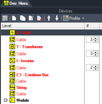
The next figure shows the basic hierarchy that Helios 3D offers on startup.
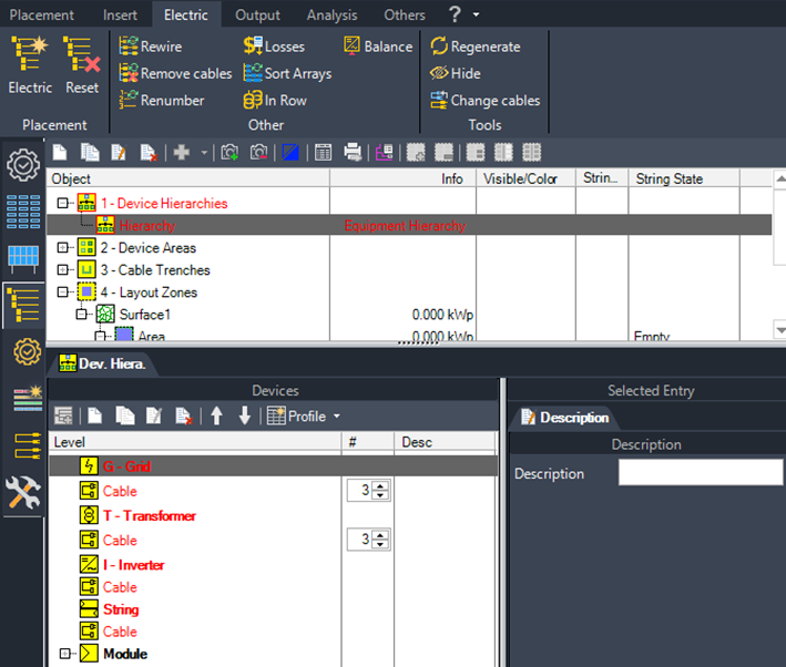
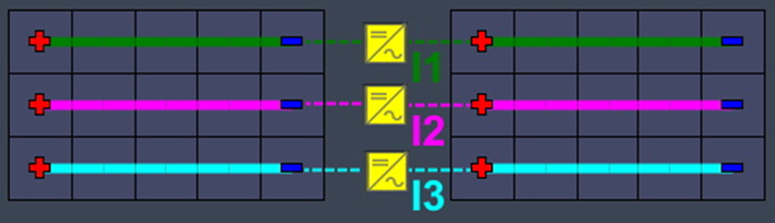
The logical hierarchy always runs from a module to the grid. A complete and valid hierarchy must be established before proceeding to the next point, „2 – Device Areas“. Typically, two hierarchies are used:
- String Inverter Hierarchy (as predefined):
- Module → String → String Inverter → Transformer → Grid
- Central Inverter Hierarchy:
- Module → String → Combiner Box → Central Inverter → Transformer → Grid
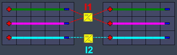
A combiner box can be inserted above the selected base element (excluding cable entries) by clicking

The central inverter hierarchy with a combiner box placed above (or logically behind) the string is shown in the following figure.
The logical hierarchy entries displayed above are device collections. You can add one or more components from the database to each of them by clicking the appropriate button. The physical devices/components should be predefined in the Component Management of the database application. However, any component, except for the grid, can also be created directly within this interface.
| The string definition should be created last, as it requires a physical inverter or a physical combiner box to be attached. |
One more exception is the „Module“ collection. In this case, Helios automatically inserts the module used from the array definition.
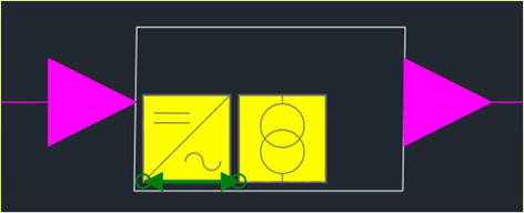
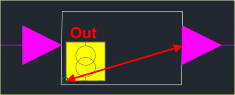
Adding an Entry
Adding an entry requires two steps. First, select the corresponding collection, such as „T – Transformer“, and then click

The entry will be marked as „invalid Article“ until the second step is completed, which involves assigning an article from the database. The following figure illustrates this step for adding a new transformer entry.
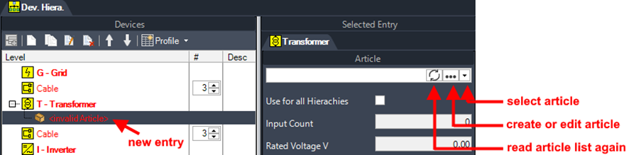
If you create a new database article, the common dialogs will appear with the corresponding component type pre-set based on the master data.
| Creating a new article/component does not work for grid connections, as a grid is not a physical component but an abstract device. Therefore, it is defined by a choice list record. |
Copy

Create a modifiable copy of the selected string definition.
Edit

Opens the dialog for modifying the selected string definition.
Delete

Deletes the selected entry.
Move Entry

Moves the selected entry one position up or down.
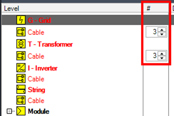
Number of Cables in AC Part
Since this information is currently not read from the cable data, you can manually add the number of individual cables used between two devices in the „#“ column.
For example, a value of 3 between the Transformer and Grid means that the distance between the devices will be multiplied by 3 for the cable length in the parts lists. If only one cable with 3 phases is used, this value should be set to 1.
String Definition
Here, you can create a string design and save it as a profile for reuse by clicking the „Save“ option at the top of the window.
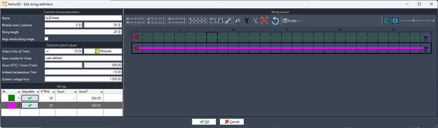
The following section describes all parameters in detail, followed by an explanation of how to wire the modules. The common string parameters are mandatory values.
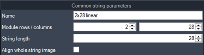
String Definition Parameters
Name
Enter the name for the string definition profile.
Module Rows/Columns
Specify the number of module rows and columns for the default string. This configuration should ideally correspond to the PV table being used.
String Length
Define the exact string length for generating predefined strings. Manually drawn strings will be marked as deviations if their length does not match the specified value.
Align Whole String Image
Aligns the entire string definition relative to the target device position. This prevents individual alignment of strings on the same table when devices are connected on different sides of the table.
Optional control values can aid the user in designing a valid electrical layout but are not mandatory and can be ignored if desired.
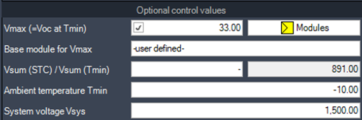
Vmax (Voc at Tmin)
The maximum voltage per module determines the maximum string length. The minimum ambient temperature is defined on the „Settings“ page of the Electrical module.
This value can either be entered manually or automatically retrieved by selecting a module using the button next to the input field. The calculation is based on the module data and is described as follows:
Vmax = Voc * (1.0 + (Tmin – 25.0°) * (TempCoeff_Voc * 0.01))
The values for the open-circuit voltage (Voc) and the temperature coefficient of Voc (expressed in % per °C) are sourced from the module specifications.
Vsum(STC) / Vsum(Tmin)
Displays the calculated string voltages for the configured standard string length under Standard Test Conditions (STC) and at the minimum ambient temperature.
Ambient Temperature and System Voltage
Shows the values defined on the „Settings“ page of the Electrical module, which are used for string configuration.
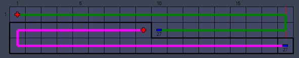
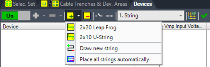
The strings can be defined either using the standard designs displayed on the modules or customized individually by clicking.
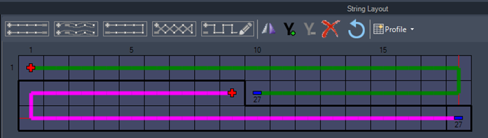
Predefined Strings

The predefined strings now need to be applied manually by clicking on the first module.
Draw Manually

Starts the mode to manually draw a string. The drawing is completed by right-clicking or pressing the Enter key.


mirror string

add / remove Y-connector

delete string

reset all strings
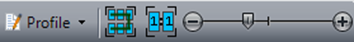
Profile management and display scaling
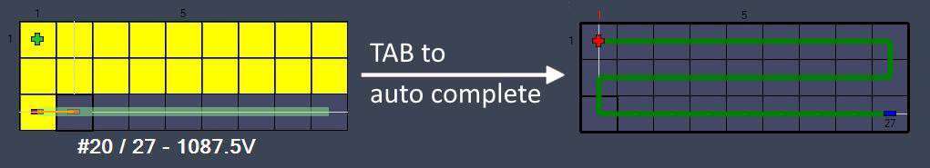
String Generator – custom string preview (2025.0.1.4)
The string generator now displays a preview in the direction of the mouse, reflecting the number of modules set per string. You can then complete the string automatically using the TAB key.
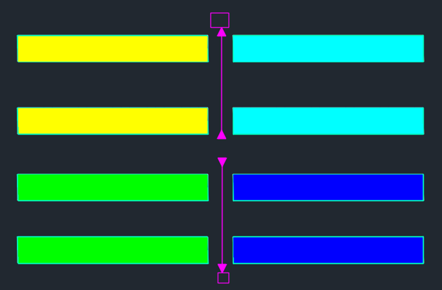
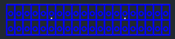
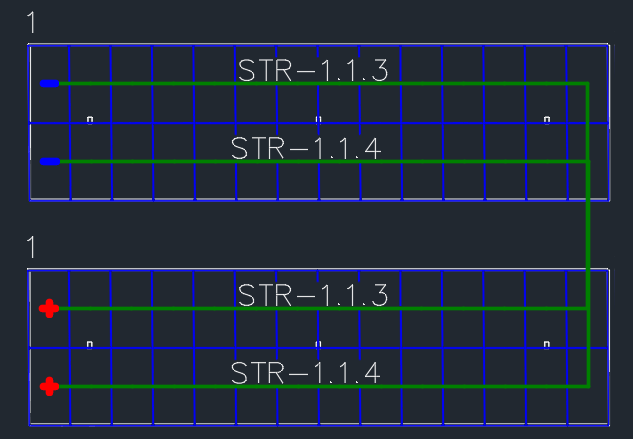
Manual strings improved behavior (2025.0.1.3)
We’ve improved the ability to delete and (re-)draw strings on PV tables, making manual designs more intuitive and reducing the risk of errors that require multiple undo steps.
Now, strings can be deleted individually without having to remove all strings from a specific table or group of tables.
In the example below, the upper string of the table on the left and the lower string of the table on the right have been removed.
| Currently, drawing strings on PV tables is limited to linear strings. However, an additional option for drawing leapfrog strings may be introduced soon through a future patch. |
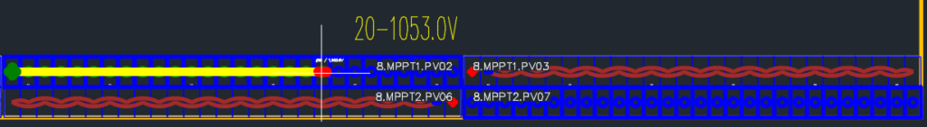
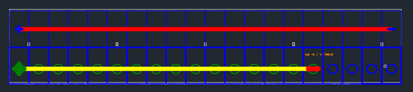
The existing option for drawing new strings on tables, as shown in the next figure,
allows users to select both tables and assign new strings to free modules. Meanwhile, the yellow-colored text indicates the number of modules that will be connected with the next left-click and displays the resulting string voltage.
Custom LeapFrog strings
It is now possible to define a leapfrog string freely likewise as the custom strings with linear design.
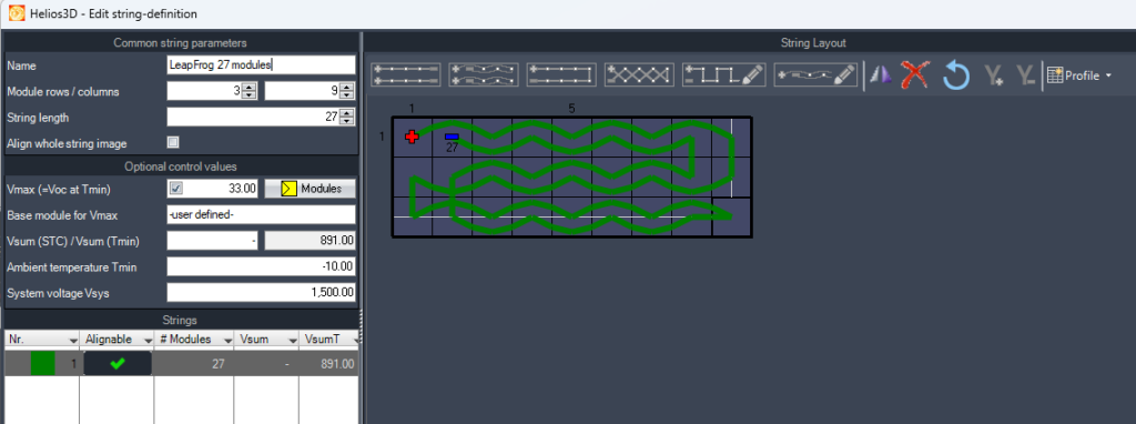
The connections between modules are simplified for better display. As the exact connection order of the modules remains unused by any function or output, there is no need for an exact representation yet.
Device Areas
Device areas are designated zones for the automated placement of grid connections and electrical devices, such as central inverters and transformers. These areas can be defined using polylines, similar to exclusion zones.
String inverters or combiner boxes are typically placed at the string or along the cable trench, so they are generally not included in this context.
Each device area must be connected to the grid; otherwise, it will be highlighted in red. In the example below, the device area without a grid connection is shown in red. The grid connection can be established through cable trenches, by linking any device area that lacks a direct grid connection to the specific grid device area.
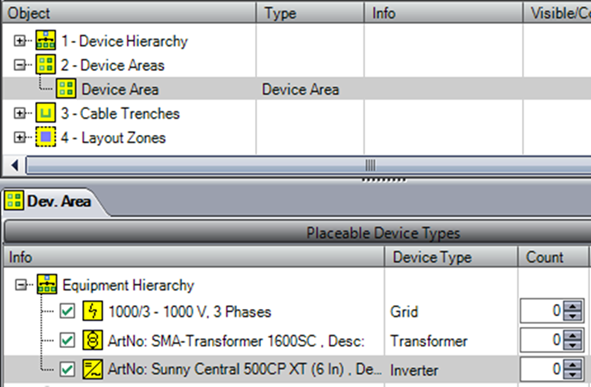
To assign devices to a device area, you can select the corresponding entries from the device hierarchy. Afterward, you can set a limit on the quantity of each specific device for that area. A value of 0 indicates no limit.
Cable Trenches
Here, you can add polylines to represent cable trenches or draw them directly. As shown in the next figure, you can also specify the depth for each trench, which will be taken into account when calculating cable lengths.
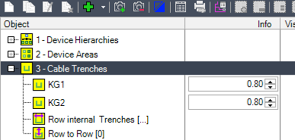
Trench 1 and Trench 2 are manually created cable trenches, whereas the „Row Trenches“ are automatically generated by Helios 3D.
Row Internal Trenches

are created when a gap occurs within a row, such as those caused by exclusion zones or exceedances of the maximum slope, and the gap is larger than the „Min. Length of Row Trenches“ value defined for the selection set.
Row to Row Trenches

can connect different rows without requiring a connection to a main trench or device area. Cables from one array row can enter this type of trench and exit at the array of another row. From there, the cables are routed to the trench specified in the trench list of the selection set.
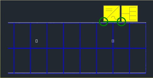
Regular cable trenches

can display the following states:
- Not connected: Indicated by an empty circle.
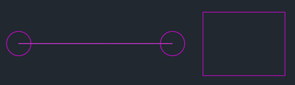
In this case, no connection to any registered device area is found, meaning that no cables can be placed into that trench.
- Connected to a device area: Indicated by a filled circle.
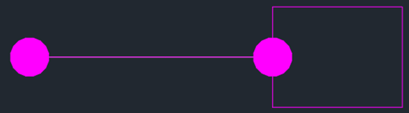
It indicates that the cable trench is properly connected to a device area, but the area itself either does not have a grid assigned or does not have any outgoing trench connected to the grid connection area.
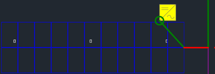
- Fully connected up to the grid connection: Indicated by an arrow.

The picture shows a proper connection to a device area with the grid assigned. The arrows indicate whether the complete connection to the grid is established directly or through outgoing trenches leading to the actual grid area. Only when this full connection is established will an electrical layout be possible.
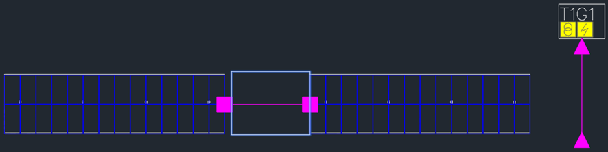
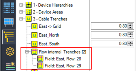
Row internal Trenches (automatically)
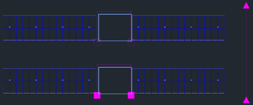
Helios 3D will automatically insert row cable trenches for gaps within a table row if the gap exceeds the value set for „Min. Length of Row Trenches.“ The endpoints of these trenches are displayed with filled rectangles.
For gaps inside a row that are smaller than this value, cables will run through the air between neighboring tables. In this case, the calculated cable length depends on the table distance and the rotation of the tables.
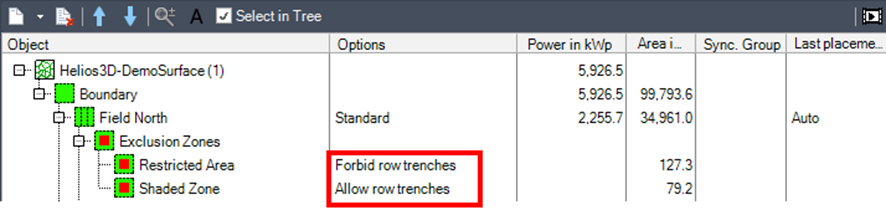
| The option to forbid row internal trenches from crossing an exclusion zone can be set during the array placement process. |
When a row trench is created, cables routed through that trench are calculated in the same way as cables in regular cable trenches.
The length calculation between the tables is as follows:
cable duct to soil + trench depth + trench length + trench depth + soil to cable duct
These trenches are listed under „Row Internal Trenches“ with the corresponding field name and row number for easy identification.
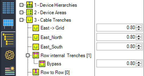
Row internal Trenches (manually)
If a direct connection through the manual row trench is not possible, you can manually insert a regular cable trench into the rows. Helios will then automatically use this trench for cable routing.
You can then assign a name to the registered polyline, such as „Bypass,“ for easy identification.
Row to row trenches
These trenches do not require a connection to a default cable trench linked to device areas. Instead, they navigate their path past the array rows. The unfilled diamond symbol represents a row-to-row trench without cables, while a filled diamond indicates that the trench contains cables.
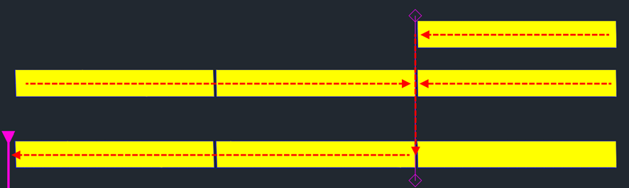
Of course, at least one of the connected rows must be linked to a regular trench.
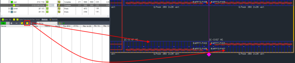
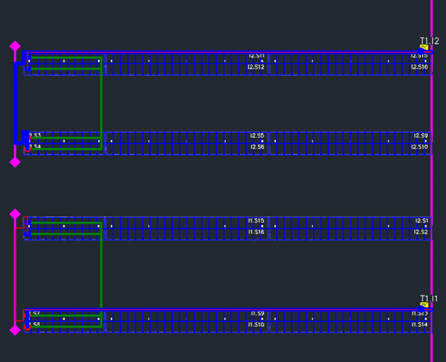
Another use for this trench type is to provide a connection for strings between PV tables from different rows. The next figure illustrates how strings run through two tables from different rows, using row-to-row trenches on the left side. Meanwhile, the inverters are placed on the right side, close to the main standard cable trench.
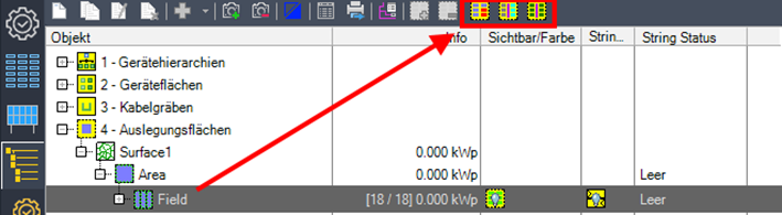
New selection set generator/editor
An improved option for generating selection sets provides direct feedback on the number of selected arrays, modules, and the resulting number of strings with the specified length. The command has been added to the toolbar on the Electric page, as shown in the next figure.
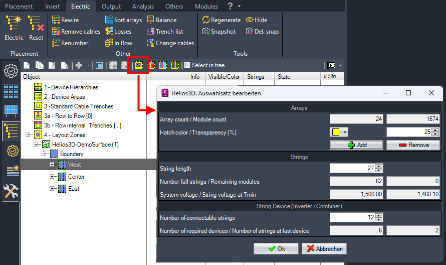
If the selected array cannot be evenly divided by the string length, the number of remaining modules will be displayed.
Based on the number of inputs of the target device, the number of required devices and the utilization of the last device are displayed for additional support.
Array count / Module count
Shows the number of selected arrays and modules.
Hatch color / Transparency (%)
Set the color for the selection set and the transparency. The transparency is just for the current selection. The final selection set will use the transparency set in the electric settings.
Add / Remove
Starts the selection command in the drawing for the user to add or remove arrays to/from the current selection.
String length
Set the length for standard strings, which will be used to show the number of full strings and open modules left for the current selection.
Number full strings / Remaining modules
Shows the number of full strings according to the set standard length and the remaining modules that don’t fit to complete another string.
Layout Zones / Selection Sets
Here, you can divide any field into different layout zones based on the positioning of cable trenches and device areas.
A general configuration must be set up for the field, as shown below. You will need to select a device hierarchy and a default string definition, and then add all cable trenches and device areas that will be used for the selected field.
The options for the field and the selection sets generated for a field are presented in the same way, so the field page can be used to predefine settings for new selection sets or overwrite existing selection sets that do not contain a placement.
First, you select one of the previously defined device hierarchies and assign a string definition to any array definition being used. These default selections will be applied to any generated selection set but can later be adjusted individually for each selection set.
Next, you must add all relevant cable trenches and device areas to the corresponding list. Cable trenches should only be added if array rows need to directly connect to them, such as DC cables or output cables from combiner boxes or string inverters that reach the first device area. Help trenches that assist with routing through the array rows to reach a device area or trenches between device areas should not be included.
The list of device areas should include any area that will receive a target device for the strings in the field, up to the grid connection, which serves as the endpoint for the electrical layout.
Selection sets for a field can be generated either manually or through three automatic options.
Rest to New Selection Set

Creates a single selection set for all arrays that have not yet been assigned to another set.
Generate Selection Sets Per Trench Side

Generates separate selection sets based on the assignment to a cable trench and the specific side of the trench.
Generate Selection Sets Per Cable Trench

Generates separate selection sets based on the assignment to a specific cable trench.
You can also create selection sets manually by clicking

while the field entry is selected. This same function can also be accessed from the context menu of the list.
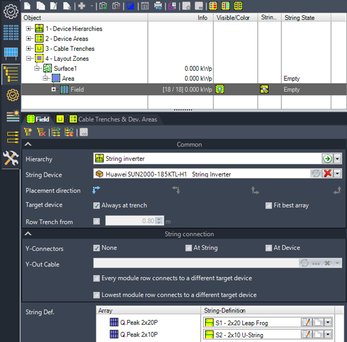
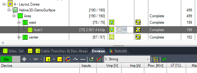
Selection sets are fundamental elements for string placement. In the next figure, you can see a list of different selection sets, including the string placement options for the selected selection set “Auto1.”
The difference between the field and selection set nodes is that, when the field is selected, you can only add or remove cable trenches and device areas from the list. For a selection set, you can specify which elements should be used by checking the corresponding checkboxes.
The entry {All Free} is displayed until all arrays are assigned to a valid selection set. This entry cannot be used for performing an electrical layout.
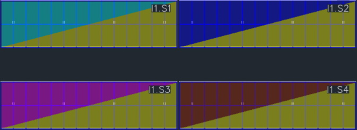
Auto# refers to the identifier for selection sets generated by Helios 3D. These can be identified in the drawing by the colors set in the „Visible/Color“ column. All tables in the drawing are marked with hatching in the color corresponding to the selection set they belong to.
You can add

or remove

arrays to/from an existing selection set by selecting the arrays after clicking the appropriate button.
The additional columns for each electrical structure tree node contain various settings and options for displaying results.
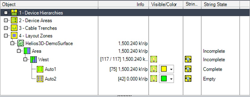
Object
Contains the main structure tree nodes, such as fields and selection sets. The icons for areas, fields, and selection sets indicate the current status of the electrical design.
Info
For some tree nodes, additional information is displayed:
- Fields: Shows the number of assigned arrays vs. the total number of arrays and the installed peak power.
- Selection Set: Displays the number of contained arrays and the power with subtracted cable losses.
Visible/Color
Allows assigning a color for the display of a selection set, along with the option to show or hide the selection set markings.
Strings
Shows or hides the module strings on the arrays.
String State
The state of an element can be displayed as one of the following: Empty, Incomplete, Complete, Rewire Needed, or Problem.
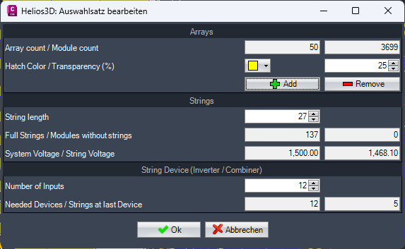
System voltage / String voltage at Tmin
Shows the system voltage from the electric system settings and the actual string voltage at the minimum ambient temperature from the system settings based on the selection and configuration.
Number of connectable strings
Set the number of inputs for your standard target device to show an extrapolation of the needed number of devices and the utilization of the last device.
Number of required devices / Number of strings at last device
Shows the number of needed devices based on the current settings and how many strings are left for the last device. A possible balancing of string connections is disregarded here.
Selection Set – string placement options
Before starting the placement for a selection set, you can:
- Select a different device hierarchy and string definition.
- Change the number of colors used for displaying the strings.
- Select (hook) or deselect (unhook) cable trenches and device areas.
Cable trenches and device areas should only be selected for a selection set when they are actually needed for the design.
Place

Start the string placement using the parameters set below.
This involves applying the selected device hierarchy, string definition, color settings, and the appropriate cable trenches and device areas for the selection set. Once these settings are in place, you can begin placing the strings according to the configured layout.
| When the placement is completed, only hatches are displayed as the result. Options for displaying the actual cables or the connections between modules and a collecting device can be found on the other tabs of the Electric module. |
Reset

To reset or delete the string placement for the selected selection set, use the corresponding option to remove the current placement. This will clear the string layout, allowing you to start over or make adjustments as needed.
Rewire

The Rewire function is used to recalculate the wiring after moving combiner boxes and inverters in the drawing with your mouse. Once the components have been repositioned, this function ensures that the wiring is adjusted accordingly to reflect the new layout.
Remove cables

The Remove Cables function removes cables between electrical endpoints, such as module strings, combiner boxes, inverters, transformers, and the grid connection. This allows all cable trenches to be modified. The assignments between objects are retained, so the Rewire command can then re-establish the electric cabling, including adjustments to existing trenches or the addition of new trenches.
Link

When multiple selection sets are selected at the same time, the button becomes enabled. This allows you to link different selection sets, enabling them to be treated as a single set.
Settings applied to one of the linked selection sets, such as using the or functions, will be applied to all linked selection sets simultaneously.
To unlink the selection sets, you must first the electrical placement before you can break the link.
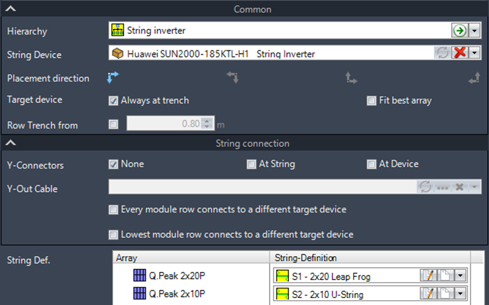
First, select a device hierarchy and a target device. These are only required if multiple options are defined, allowing you to choose the appropriate configuration for the electrical layout.
Set the placement direction for the wiring and numbering of cables and devices using the arrow buttons.

These arrows allow you to define the orientation and sequence of the placement, ensuring the correct layout for the wiring and device arrangement.
Target devices can either be placed at the optimal array, which minimizes the input cable lengths, or the optimization can be restricted to using only the first arrays from the cable trench. This option allows for flexibility in balancing cable length optimization with specific layout requirements.
Row Trenches from
Enter the distance at which cables are no longer allowed to be routed through the air between neighboring arrays. Helios 3D will automatically create a row trench within a row of tables if the gap between neighboring tables exceeds the specified value. For smaller gaps, the cables will be routed through the air, and the cable length will be calculated based on the connection points of the cable ducts of the neighboring tables.
Y-connectors at string or at device
If Y- or multi-connectors are defined in the string definition, this option adds the connectors either at the end of the string on the array or at the input of the target device.
Every module row connects to a different target device
With this option, strings from different module rows are always connected to different target devices. Strings that span across two module rows are not supported by this function.
Lowest module row connects to a different target device
The string from the first (lowest) module row can be connected to a different target device to avoid losses caused by shading. Strings from all other module rows will connect to the same target device. This configuration helps optimize the system’s performance by minimizing the impact of shading on the first row.
String Definition
Here, you can change the assignment of the string definition for any array used in the selection set. This allows you to customize how strings are defined and assigned to the arrays within the selected set.
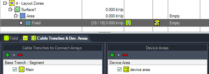
Cable Trenches & Device Areas – asignment of trenches and areas
Here, you can set the assignment more specifically for each selection set. To add or remove entries from these lists, you need to select the field node. For the current selection set, you can only (un)check individual entries to determine which ones will be used.
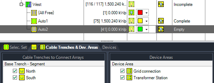
Cable Trenches to Connect Arrays
A cable trench should only be selected (hooked) if strings need to be directly connected to it. Selecting additional strings, such as those between device areas, can cause issues if these trenches run (partially) in parallel.
To add or remove entries from the list of cable trenches, please return to the field options.
| Cable trenches that are only used for connecting two device areas are never needed in this list. Only select trenches that are directly involved in connecting arrays to target devices. |
Device Areas
All device areas can remain hooked if the current selection set is intended to place target devices in all of them. For more complex scenarios, you can modify the check states to specify a particular transformer station for string inverters from the current selection set or handle similar situations where different device areas are required for different components.
| For the hooked device areas, there must be a clear and unambiguous assignment between the electrical devices and the device areas. If this assignment is not clearly defined, the placement will be canceled. This ensures that each device is correctly assigned to its respective area without any conflicts. |
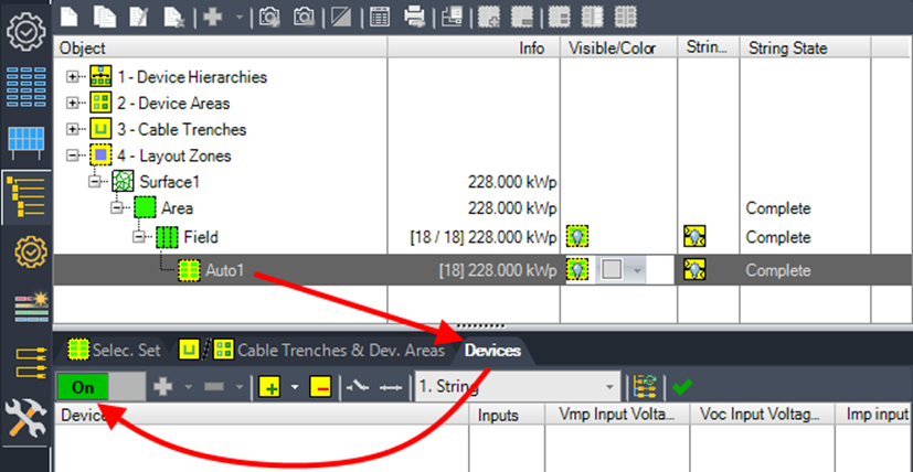
Page Devices (manual electric)
The manual electric functions are located on this page. It allows for manual adjustments to the automatic electrical placement or enables the manual insertion of strings and devices. Further details and instructions can be found in Chapter „Manual Electric„.
Manual Electric
Strings can be connected to or disconnected from their target device within the selected selection set. To connect strings to a target device, the device must either have unused inputs available or require existing connections to be disconnected beforehand.
The <On/Off> switch temporarily disables sections of the HELIOS 3D palette when the connection editing mode is active.
| Once all changes have been completed, this function must be switched off again. |
| The commands on this page outline the expected steps as they appear in the AutoCAD command line. |
Manual Strings
In string mode (always the first point on the list), all existing strings are displayed in the tables. Strings shown in red are not connected to any target device, whereas connected strings adopt the color of their corresponding string inverter or combiner box.
The Create String button

allows you to assign a string to a table with available free modules, while the Delete String button

enables you to remove existing strings.
The String List

displays all strings defined within the device hierarchy, which can then be applied to a group of tables selected using the mouse cursor.
The Manual String Tool

allows you to select a table or a group of tables and manually draw strings within the table layout. Blue circles will appear on any free module in the selected tables, indicating available modules for string assignment.
By selecting the blue circles, you can draw a string. Pressing the key or performing a right-click completes the current string. If additional free modules are available, the manual drawing mode continues; otherwise, the mode ends automatically.
The next image illustrates a fully drawn but unconnected string in red and an incomplete string in yellow.

This function executes the automatic string placement based on the configured placement options, overwriting any existing strings. You can choose to create all strings manually or utilize this auto-generator feature and make adjustments to the results afterward.

Once all tables in the selection set have been assigned strings, this button can automatically finalize the electrical layout by adding combiner boxes, inverters, and other devices from the hierarchy. The process adheres to the automatic placement algorithm.
Alternatively, you can perform all other electrical steps manually by navigating through the hierarchy levels step by step.
Reassignment of connections per Drag & Drop
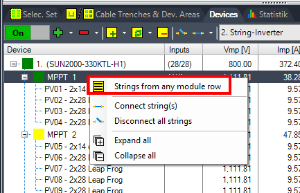
The figure below illustrates a leapfrog string being dragged to an already used input. As soon as the target input is recognized, it is highlighted in bold letters to indicate the current selection.
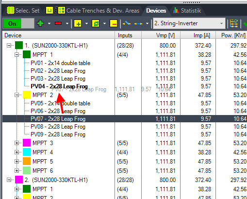
During the reassignment of strings to inputs, the predefined placement rules are applied. If a user attempts to connect strings from different module rows to the same MPPT, they may need to temporarily suspend this rule using the command shown in the next picture.
For higher levels as inverter to transformer or transformer to grid assignment, drag & drop is available as well.
Insert Devices manually
To insert a device manually, you must first select the corresponding hierarchy level.
The example below illustrates a string inverter hierarchy without any combiner boxes.

This function allows you to select devices in the drawing, adding them to the list for connecting the strings.

This function removes devices from the list.

This function provides a list of devices from the device hierarchy for the selected hierarchy level. Devices that are added to the table rows can be inserted using your mouse. Other devices are immediately inserted into the designated device area for the selected set.
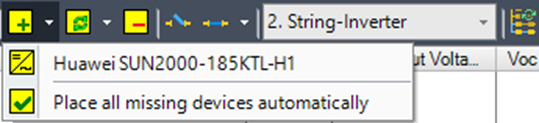
The last entry will place all missing string inverters (devices from the selected hierarchy level) based on the automatic placement algorithm.

This function provides a list of devices from the device hierarchy to replace the current device in the drawing.
| To add alternative components to the device hierarchy, you must temporarily switch off the manual electrical mode. |

This function deletes devices from the drawing.

This function allows you to disconnect or connect strings to a string inverter. For a transformer, it is used to connect or disconnect the input device.
When connecting strings, you can:
- Assign the selected strings to the target device that is preselected in the tree list,
- Or wait for the user to select a target device in the drawing and press or right-click again to confirm.

This function starts the rewire command to recalculate the cable routing.

Once the current hierarchy level is complete, such as when all strings are connected to their respective string inverters, you can automatically finalize the electrical layout.
| Changing connections must be finalized by turning the switch back to the off position. |
New commands
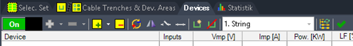
The manual electric module offers new commands in the toolbar.
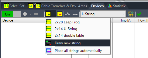
New options for adding strings with

have been added to the context menu, as you can see in the next picture.
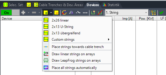

Place strings towards cable trench (only users with Beta access)
Opens a dialogue for generating strings to groups of arrays targeting at a selectable trench. The strings are generated from the outer arrays of a row towards the cable trench using all modules independent from the table units. The same string can cross tables of different sizes without leaving gaps.
Around the cable trench, tables that no longer fit into the layout are left out.

Draw linear strings on arrays
Allows you to select a table or a group of tables and to draw strings manually inside the table layout.
Blue circles appear in any free module of the selected tables.
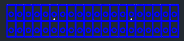
By selecting those circles, you can draw a string. The <Enter> key or a right-click completes a string. If more free modules are available, the manual drawing mode is continued, otherwise the mode ends.
The next picture shows a completed but not further connected string in red color and an incomplete string in yellow.


Draw Leapfrog strings on arrays
Allows the user to draw leapfrog strings freely on the selected arrays, as it was already possible to do for linear strings.
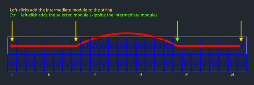
| Auto connection of intermediate modules with Ctrl + Left Click If the modules between the last selection and the next module should not be added to the string automatically, hold the Ctrl key while clicking to the next module. |

Runs the regular string placement according to the automatic placement options, which will overwrite the existing strings. So, you can either do all strings manually or use this auto generator function and afterwards change the result.
Other Toolbar buttons
The rest of the toolbar buttons displayed below other than

and

have the following meanings.

Swap polarity (only users with Beta access)
Changes the polarity of a string so that plus and minus poles are swapped. Right now, this function is only usable for strings that aren’t connected to a target device, such as a string inverter.

Mirror string (only users with Beta access)
Mirrors a string across its center axis. By now, strings get disconnected from their target device in the process.

Assign string to trench
Allows to assign a string individually to a trench other than the default trench picked by the algorithm.

Undoes the manual assignment and uses the default algorithm to detect the target trench for a string.
Electric – Settings
On this page, you can configure general settings for the Electric module. The cable lengths defined here cannot be calculated. Any changes to these length values will be applied to existing electrical placements, updating the total lengths and losses of the electrical structure accordingly.
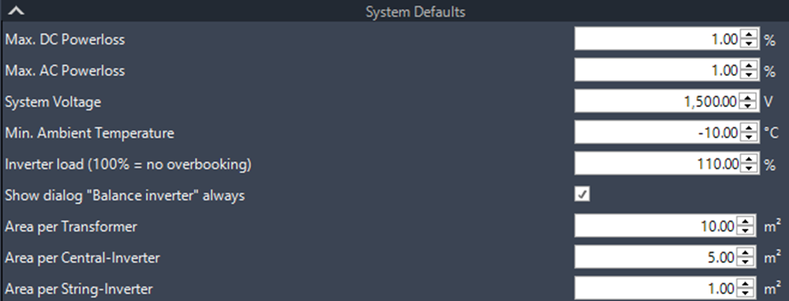
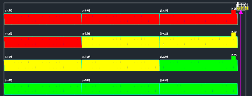
Max. DC and AC Power Loss
When the specified power loss value for the corresponding current type is exceeded, the cable is highlighted on the Electric Structure page to alert the user about potential design issues. The maximum power loss is evaluated for both the module string and the sections between devices such as combiner boxes, inverters, transformers, or the grid. Note that this does not represent the total loss up to the current node in the structure tree.
System Voltage
This refers to the target system voltage for the electrical layout. It is used for verification and triggers warnings if the system voltage is at risk of being exceeded—such as with certain device combinations in the hierarchy or long strings paired with high-voltage modules.
Min. Ambient Temperature
The minimum ambient temperature is used as the baseline for determining the maximum string length possible for the selected module type.
Inverter Load (100% = No Overbooking)
The inverter load defines how many strings will be connected to an inverter. At 100%, Helios 3D will utilize the exact inverter specifications and stop connecting strings once the limits are reached. Values above 100% allow for overbooking under Standard Test Conditions (STC).
Show Dialog “Balance Inverter” Always
This option ensures that the dialog for balancing inverter input usage is shown during electrical placement if the last inverter has fewer strings left to connect than available inputs. It allows the user to balance the input use of multiple inverters before finalizing the electric layout, thus avoiding manual adjustments after placement.
Areas for Devices
The areas for devices like transformers or inverters are included in the PV table placement statistics, alongside other areas such as fences, roads, and the PV design coverage ratio.
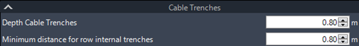
Depth Cable Trenches
This is the default value for new cable trenches. On the Definition page, you can modify the depth for any individual trench as needed.
Depth Row Trenches
This is the default value for new row trenches. On the Definition page, you can change the depth for manually created row trenches, but the depth cannot be modified for automatically generated trenches.
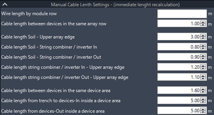
Wire Length by Module Row
This value represents the cable run between the cable ducts and the connection points of the module rows. If there are multiple values, they correspond to the module rows starting from the front and extending to the back. Each value must be separated by a semicolon.
Example: 1.9;0
This means:
- Extra cable required for the 1st module row: 1.9 units.
- No extra cable required for the 2nd module row: 0 units.
In this case, the first module row needs additional cable, while the existing cable for the second module row is sufficient.
Cable Length Between Devices in the Same Array Row
This value is used, for example, when a DC combiner box and a string inverter are inserted into the same table row. In such cases, the cable length between the combiner box output and the inverter input is defined by this value.
Cable Lengths Soil – Upper Array Edge
This refers to the cable length from the soil to the cable duct on the table. Since this distance can vary greatly based on the layout, it is not calculated automatically. For consistency and independence from the post layout, underground cables are assumed to start and end at the center axis of the table and at the closest point to the trench.
Cable Length Soil – String Combiner / Inverter Input
This refers to the cable length from the connection point at the soil to the input of the DC combiner or string inverter. The connection point at the soil is the nearest point to the trench along the center axis of the table. This value is used for cables that utilize a trench to reach the target device in a rack structure.
Cable Length Soil – String Combiner / Inverter Output
This refers to the cable length from the output of the DC combiner or string inverter to the soil. The connection point at the soil is the nearest point to the trench along the center axis of the table. From this point, the cable continues vertically to the depth of the trench it connects to.
Cable Length String Combiner / Inverter Input – Upper Array Edge
This refers to the cable length from the input of the DC combiner or string inverter to the upper edge of the array where the device is located. Incoming string cables from the same table row are always displayed along the upper edge of the array, and this value accounts for the distance down to the actual device position beneath the table.
Cable Length String Combiner / Inverter Output – Upper Array Edge
This refers to the cable length from the output of the DC combiner or string inverter to the upper edge of the array where the device is placed. This value is used for cables that run from the device output back to the upper edge of the array, in cases where the cable does not go directly to the soil to enter the nearby trench.
Cable Length Between Devices in the Same Device Area
This value represents the cable lengths between devices located within the same device area. No additional cable lengths will be calculated for connections inside device areas.
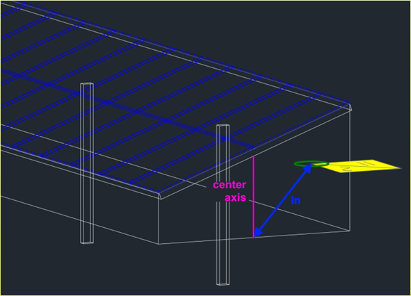
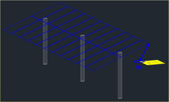
Cable Length from Trench to Device-In Inside a Device Area
This value represents the cable length from the trench to the device input inside a device area. The length calculation ends at the device area border on the surface, and this value is added on top, regardless of the device’s position within the device area.

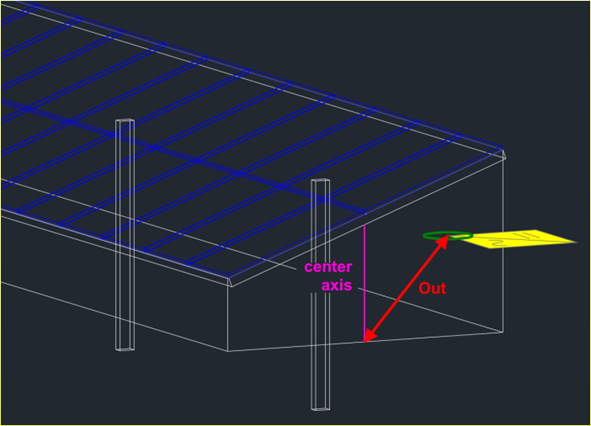
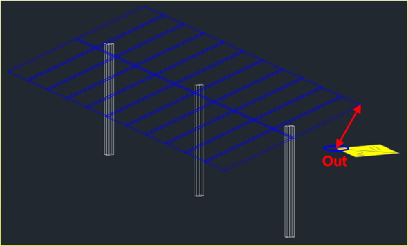
Cable Length from Device-Out Inside a Device Area
This value represents the cable length for outgoing cables inside a device area. The length calculation starts at the device area border on the surface, and this value is added on top, regardless of the device’s position within the device area.
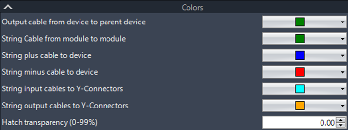
The selected colors are used to display cable segments. The hatch transparency for temporary objects helps prevent the rectangles or triangles used for selection sets and string layouts from fully covering arrays and string texts, ensuring better visibility and clarity.
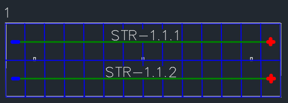
Centered String Labels
The Electric settings page now includes new options for setting the insertion position of string labels, allowing them to be placed at the center of a string or at any part of the string across multiple tables.
To apply these changes, the labels must be refreshed either through a new placement or by using the „Renumber“ command.
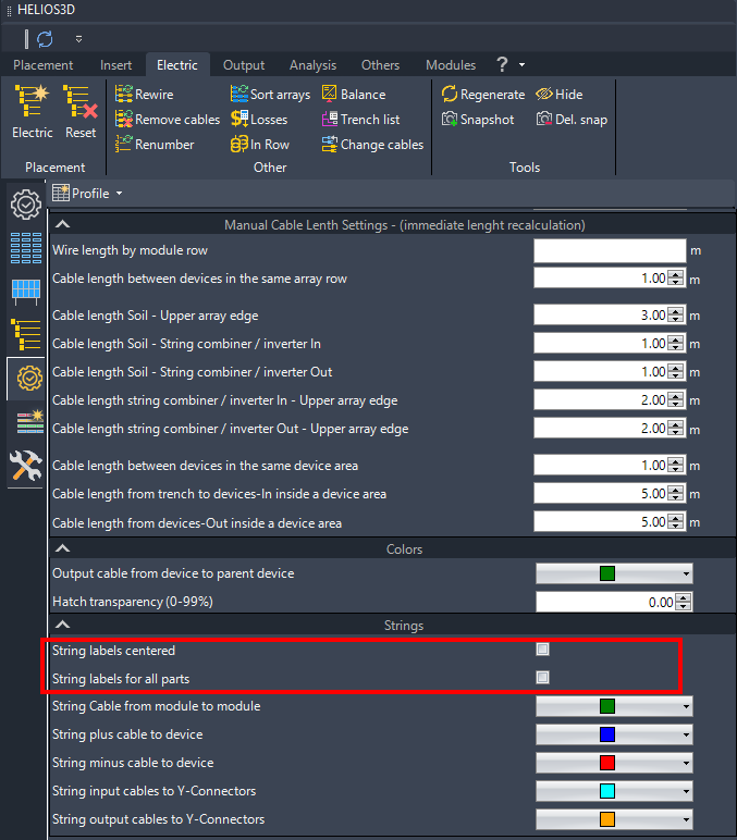
String labels centered:
String labels for all parts:
Electrical Structure Tab
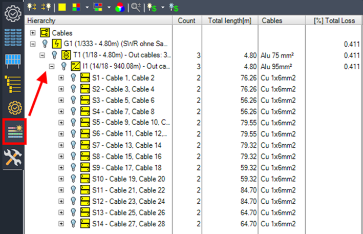
On the Electrical Structure tab, you can view a cable list and toggle the visibility of layers for cables connected to the selected electrical device. For each cable, you can find details such as the number, length, and specific type.
Show/hide all outgoing cables

This option shows or hides the outgoing cables of the selected entry.
Show/hide all ingoing cables

Shows or hides ingoing cables of the selected entry.
Show modules

This option shows all modules connected to the selected object in the same color.
Show modules of devices

This option shows all modules connected to the selected object in the same color. When multiple objects are selected, a separate color is used for each object and its connected modules.
Show modules of parallel devices

This option shows all modules connected to the selected object in the same color. If the object has parallel connected objects with the same parent (e.g., string inverters sharing the same transformer), a separate color is used for each parallel object and its connected modules.
Change color

This option changes the color for the selected entry.
Zoom to object

This option zooms in on the selected object.

This option shows or hides the colors on modules indicating the maximum loss of a module string, array, or inverter.
Cables Node
This lists all cable types used in the drawing, including their total length.
G1 – Grid Node
This lists any device used in the structure tree, allowing you to toggle the visibility of layers for individual cables or for all cables connected to the selected electrical device. If multiple grid connections are used, there will be more than one grid tree listed.
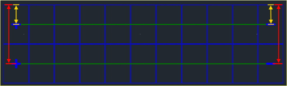
Calculation of Cable Lengths
Please note that there are two basic cable sections. In the first section, Helios 3D uses two single wires—one for each path/direction. In the second section, a twin wire is used for both directions. These two sections are clearly separated by the combiner box or string inverter. The distinction between the sections is illustrated in the drawing for easier understanding.
Single Wire / Twin Wire
For the wiring between the module strings and the combiner box (or string inverter), Helios 3D uses single wires for each direction. One wire carries the positive („+“) connection from the module string to the back end of the table and to the combiner box connection point, while the other wire carries the negative („-„) connection from the module string.
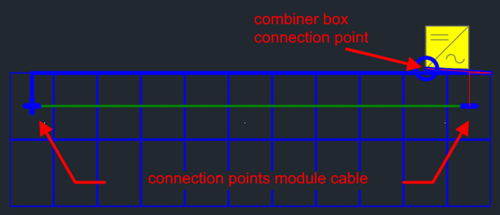
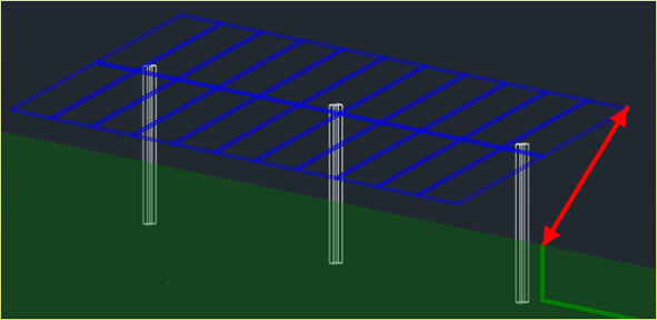
From the combiner box or string inverter (target device), you can configure the device hierarchy to specify how many physical cables are used for the outgoing phases. When the target device is placed on a table that isn’t next to the cable trench, the cable is routed back to the cable duct on the table.
If the table is the first one next to the trench, the value set on the Settings page inside the Electric module is used to determine the cable distance between the device output and the ground. The following figure illustrates this distance. The calculation for the cable continues from the closest point on the ground to the trench, along the center axis of the table.
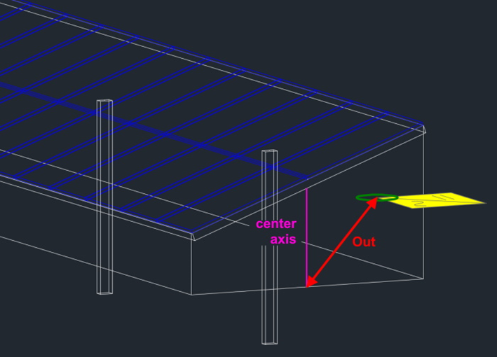
From the ground point, the cable is routed vertically to the trench depth and then to the cable trench.
At the device area, the cable is routed vertically from the trench up to the ground.