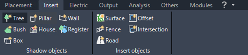
Insert
Here you will find functions related to the modules‘ shading effects.
The Insert ribbon contains tools for adding auxiliary planning objects, terrain-related objects, and shadow-relevant objects to a Helios 3D drawing. These objects support the preparation of PV layouts by representing real-world elements such as trees, pillars, bushes, houses, walls, fences, roads, and surface boundaries.
Use this page when you need to add objects that influence shading, terrain preparation, accessibility planning, or exclusion areas before or during array placement.
Various predefined objects can be inserted as shadow-casting elements. Depending on the object, you can set its length, height, and width in the dialog that appears. We describe this in detail in Section „Shadow Objects“.
Only the wall object requires a predefined polyline. Its options dialog allows you to set the segment length for the surface base points and the height above ground.
You can also register your own objects. For more details, please refer to Section „Shadow Objects“.
Command Group Shadow Objects
The Shadow Objects command group is used to insert or register objects that may cast shadows on PV modules. These objects are relevant for layout evaluation and shading-related planning decisions. Depending on the selected object type, Helios 3D may request dimensions such as height, width, length, or a predefined polyline.
Typical use cases include trees, poles, buildings, bushes, walls, fences, forest edges, or simplified obstacle representations
Insert tree

Inserts a tree as shadow object.
Insert pillar

Inserts a pillar as shadow object.
Create wall alongside polyline
Use this command when a linear obstacle must be represented as a shadow-casting object. The required polyline should follow the intended wall, fence, forest edge, or boundary line before the command is started. Longer segment lengths can reduce the number of generated surface points and may improve performance in large projects.

Generates a wall for shadow calculation alongside a polyline that needs being created in advance. This can also be used as abstract simplification for fences or forests.
It’s recommended to use big segment lengths and split surrounding walls into pieces for faster calculations. The result lines might be arranged better as well.
Insert bush

Inserts a bush as shadow object.
Insert house

Inserts a house as shadow object.
Register as shadow object

Registers an AutoCAD object as shadow object.
Insert box

Inserts a box as shadow object.
Command Group Insert objects
The Insert objects command group provides tools for creating or modifying planning geometry that supports the PV layout workflow. These tools are not limited to shading. They can also be used for terrain preparation, surface boundary handling, access roads, fences, and exclusion-zone related planning.
Use these commands before or during array placement when additional geometry is required to describe the site conditions more accurately.
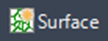
Create rectangular surface
This function is intended for early project preparation when no detailed survey surface is available yet. The imported surface can provide a quick terrain basis for preliminary layout work. Because the web-based data has a low resolution, it should not replace a validated survey model for final engineering, grading, or construction documentation.
Important:
The drawing must have a suitable coordinate system and map background setup before the surface area can be selected correctly. The imported TIN surface is limited to a maximum size of 10 km² according to the current page content.
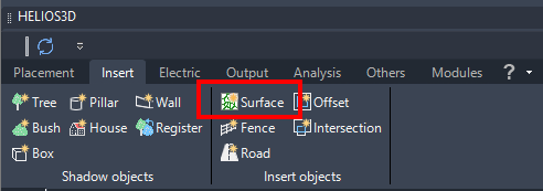
A new Insert option is available for retrieving a surface from the web with a low resolution. This function imports data from https://www.gpxz.io/, which is an included alternative to third-party plug-ins that can be added to Autodesk Civil 3D.
If a coordinate system is set and the Bing map shows in the background, you can navigate to a location and select the area you want to retrieve data for with a rectangular selection.
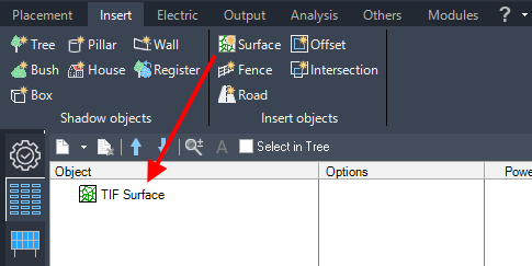
The function is located in the “Insert” page on the Helios 3D palette as displayed below.
Starts the import command and shows the following prompts in the AutoCAD command line.
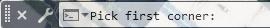
The user can pick the first corner of the area which immediately leads to the next prompt.

The result will be a rectangular TIN surface at a maximum size of 10 km². The surface immediately is ready to be used for creating a layout.
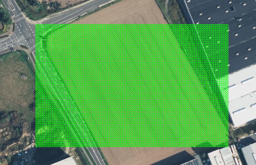
The surface immediately appears to the array placement page as the next picture shows.
Offset surface border
Use this command when the border of a DTM surface needs to be reduced inward by a defined distance. This can be useful for avoiding unreliable edge areas of imported or surveyed terrain data. The command is required because the DTM border is a 3D polyline and cannot be offset with the standard Civil 3D offset command.
Typical check:
If the result does not appear as expected, verify the selected DTM border, the entered offset distance, and the drawing units.

Offsets the DTM border inward. After clicking, you will need to enter the offset distance in the command line.
Since the DTM border is a 3D polyline, the standard offset function in Civil 3D does not apply.
Create fence
Use this command when a fence must be represented along an existing polyline. The fence can be displayed in a simplified hatched form or as a more detailed 3D-area representation. A detailed display may provide a more realistic visual result, but it can also increase drawing complexity and resource usage.
Recommendation:
For large projects, use the simplest display option that is sufficient for the current planning task. Add posts only when they are needed for visualization, documentation, or project-specific coordination.
Calls the dialog for creating a fence along a polyline. Before the dialog is displayed, you get prompted to select the polyline in the command line.
The following figure illustrates the parameters provided for this fence:
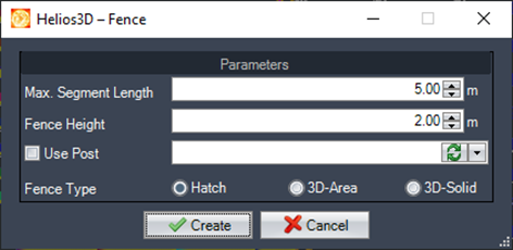
- Max. Segment Length
Here, you can specify the maximum segment length in meters. All segments will adhere to this length, except for those at the corners of the fence, where the segment length will be shortened to fit. - Fence Height
Please enter the height of the fence in meters here. - Use Post
If you activate (check) this option, you can choose a post definition from the list. The selected post will be displayed in the drawing after insertion.
If necessary, you can refresh the list by using the refresh button. - Fence Type Hatch / 3D-Area
Here you can choose a display type for the fence. The ‚hatched fence‘ is a simpler display option, while the <3D-Area> display type is more detailed and realistic, though it is more resource-intensive.
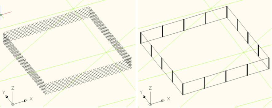
The following figure illustrates the difference between a fence with minimum display accuracy (hatch without posts) and maximum display accuracy (3D-area with posts).
Create intersection line
Use this command to create a road object along an existing 2D polyline. The road can be generated as a 3D volume, and an optional exclusion zone can be created around it. This is useful when access roads, maintenance paths, or internal site roads must be considered during PV layout planning.
Planning note:
When an exclusion zone is created, check the name and offset distance carefully. The resulting exclusion geometry may affect later array placement and available module area.
Creates a polyline out of the intersection between either two polylines or a polyline and the DTM border.
First, select a polyline, then select the second polyline or the DTM surface. The command line will display the required instructions.
Create road along polyline

This opens a dialog for creating a road along a 2D polyline. The polyline must be selected, unless it is already preselected. The road will be created as a 3D volume.
Additionally, you can optionally create an exclusion zone around the road.
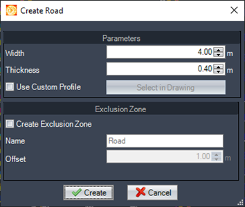
- Width
Define the road width. - Thickness
Specify the thickness of the 3D volume. - Use Custom Profile
Activates the selection button to choose a 2D polyline as the profile for the road. - Select in Drawing
Select a polyline in the drawing to use as the road profile. The width, thickness, and volume of the road will be generated accordingly. - Create Exclusion Zone
Creates an exclusion zone with the specified name and offset value set below. - Name
Enter the name for the exclusion zone. - Offset
Enter an offset distance for the exclusion zone. The polyline will be created around the road.