How is the calculation of the row distance / shadow cast?
The row distance calculation is based on the shadow cast by the front row of modules, with the end point of the shadow ray that extends the farthest into the terrain (in the north direction) serving as the basis for determining the position of the next row. Here’s a breakdown of the necessary settings and parameters:
Needed Project Settings:
- Date / Time as Reference for Placement: This is the reference for calculating the shadow’s angle. The default setting is June 21, at 12:00 PM (solar noon), when the sun is at its highest point in the sky. However, this can be adjusted for different seasons or times of the year.
- Geographical Position: The latitude, longitude, and time zone of the project site are required. These factors determine the angle of the sun at any given time and day, which affects the shadow length and direction.
Needed Placement Settings:
- Array Model: To calculate the shadow and row distance, the following array properties are needed:
- Module measurements: The dimensions of the individual modules (width and length).
- Number of rows and columns: The array’s configuration (how many rows and columns of modules there are).
- Rack overhang: The overhang on each side of the module plane, which could affect the shadow.
- Distance between the front edge of the first row of modules and the surface: The clearance or gap between the module row and the ground, which also influences the shadow’s behavior.
- Module Inclination: The angle at which the modules are tilted from the horizontal surface, as this will determine the length and direction of the shadow cast by each row.
In this calculation process, the shadow cast by the front row of modules determines the row distance for the next row of modules. Here’s a more detailed breakdown of the process:
- Sun Ray/Vector Calculation:
The angle of the sun ray is determined based on the project’s settings. This includes the geographical position (latitude and longitude), time zone, date, and time. The angle is calculated using AutoCAD, which accounts for the sun’s position in the sky relative to the terrain. - Array Model for Calculation:
The array (module layout) is treated as a box for calculation purposes. This model includes the dimensions of the module array, the number of rows and columns of modules, and other layout parameters. - Adapting the Array to the Surface:
The front edge of the array is aligned with the terrain. The bottom corners of the front row modules are adjusted to the row line, while taking into account the height of the terrain surface. This ensures that the array is correctly positioned relative to the natural contours of the land. - Distance to the Next Row:
- With Overhang: If the array has a set overhang (distance from the edge of the array to the ground), this value is used to calculate how much shadow the front row will cast on the next row.
- Without Overhang: If there is no overhang specified, the outer corners of the rear of the array (the „upside“ of the module) are used to determine the shadow projection.
- Shadow Ray Projection:
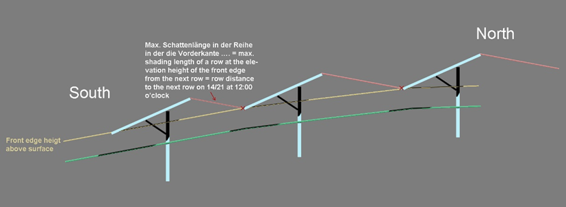
A shadow ray is projected from each corner of the front row of modules into the terrain. The endpoints of the rays are where the shadow will fall on the surface. To calculate this, the virtual surface of the terrain is raised to the height of the front edge of the array. - Safety Premium:
If an installation tolerance is included (for example, a safety premium to account for slight inaccuracies in installation), the terrain surface is lowered by this tolerance value. This ensures the calculation accounts for possible errors in placement. - Longest Shadow Ray:
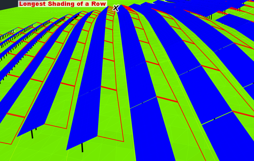
The longest of all the shadow rays cast by the front row is used to determine the distance to the next row. This longest shadow defines the minimum space required to avoid shading from the front row onto the next row of modules.The length of the longest shadow ray (as shown in the figure) is the key measurement that defines the row distance.
If a safety margin is applied to the installation tolerances, the virtual terrain will be adjusted by this value. The longest ray in a row will be used to calculate the distance to the subsequent row. As illustrated in the figure below, the length of the longest ray (indicated by a cross) determines the distance to the next row.