SLD Description
General information
Helios 3D now has functions for creating single-line diagrams. This simplifies the work and requires completed electrical layout. The SLD is created from the electrical tree generated by the electrical layout and its level of detail can be controlled by the user. The representation is not based on specific international or national standards. If this should be necessary for the symbols, they can be adapted accordingly by the user. The diagram uses Helios 3D symbols for automatic creation. With additional help functions and the description of the Helios 3D symbol system, the user can supplement the symbol library with their own, company-specific, more complex symbols. These can then be inserted interactively.
SLD philosophy Helios 3D
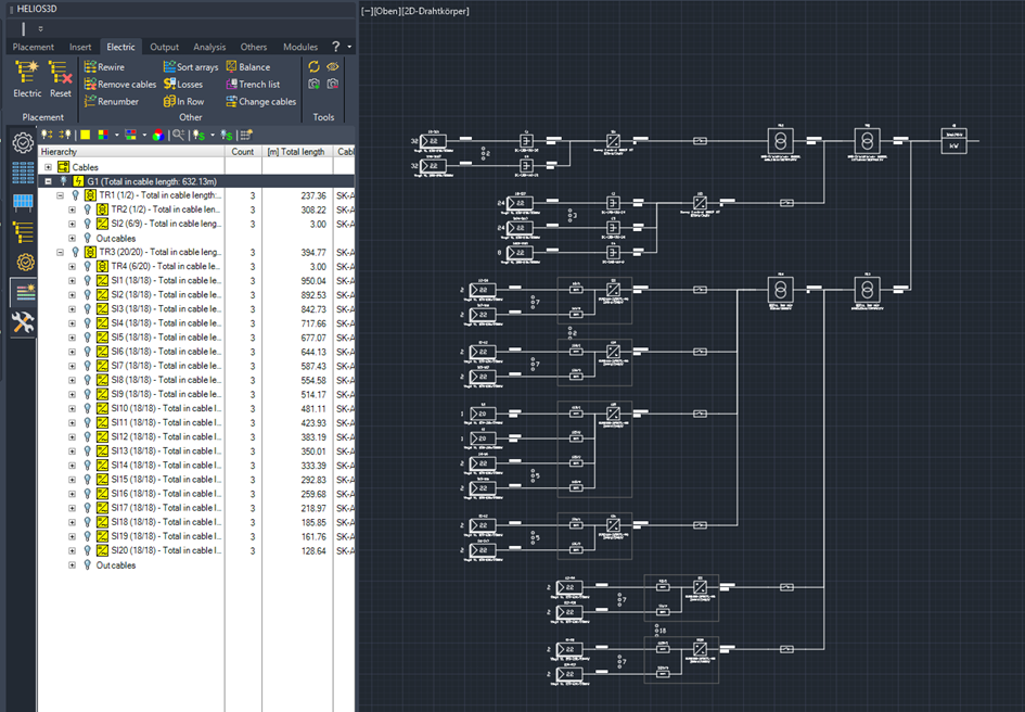
The Helios 3D SLDs are generated based on the electrical structure created with the electrical system. The SLD is a direct representation of the electrical tree. At the same time, the electrical tree serves as a preview of what the function should draw. Depending on which parts of the electrical tree are expanded, and which details are visible, the SLD is drawn accordingly.
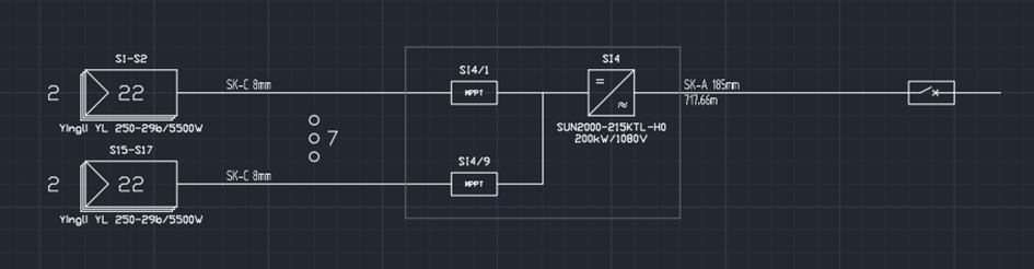
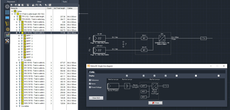
The SLD displays the information from the electrical tree and uses data from the device database to supplement the SLD. Identical elements can be summarised and thus the display height can be shortened. If more than 3 identical structures are found, they are summarised and thus shortened. Here are for example a total of 9 identical elements and 7 have been summarised.
Where can I find the SLD function?
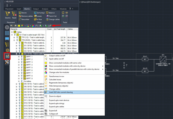
The function is subordinate to the icon for displaying the electrical structure and is called up using the marked icon.
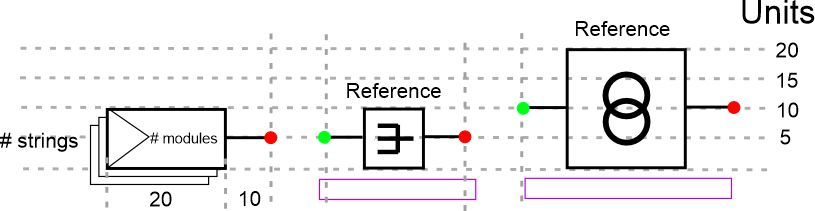
Basics
The function uses predefined symbols for the parts used directly by Helios 3D. The H3D-SLD directory contains the Helios 3D SLD symbols and can be extended with your own SLD blocks. However, these are not inserted by Helios 3D, but by the user. The SLD symbols are based on a grid of 5 units. This ensures that the elements have a systematic size and can be arranged in a more structured way, thanks to the additional snap grid of 5 units. The connection points (input, output) always lie on such a grid point and have a 10 unit long horizontal connection to the actual symbol. The block is attached to this when it is inserted and the snap grid is switched on. Customised symbols created by the user should also have this system, so that they can be used more easily together with the Helios 3D symbols.
The symbols use a layer structure in order to use the elements of the symbol in a targeted manner or to be able to show and hide them.
The following layers are used:Prefix: H3D_SLD_
H3D_SLD_Draw: Insert layer for the symbol block, lines and connections
H3D_SLD_Input: Layer for the symbol input (green circle)
H3D_SLD_Output: Layer for the symbol output (red circle)
H3D_SLD_Bounding Box: Frame around all symbol elements, for later collision control
H3D_SLD_Name: Layer for the variable attributes for cable type, product name, length, etc.
H3D_SLD_Reference: Reference to the designation in the electrical tree in Helios 3D
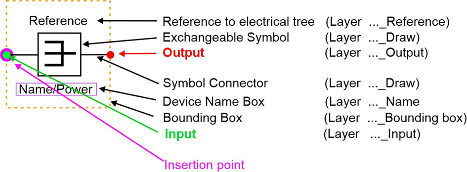
The insertion point should be on the input circle of the symbol. This allows the symbol to be inserted precisely in the grid
Customised symbols
Helios 3D generates a Helios 3D-specific SLD with its own symbols. Many users have their own function blocks in their layouts, which are not available in Helios 3D. However, the user can create any complex symbols and use them to manually supplement or change the Helios 3D SLD. If they adhere to the Helios 3D layer structure and system described above when creating them, they can use some elegant auxiliary functions that are planned for the future.
These include line functions to make it easier to connect elements with each other and the automatic redrawing of certain connecting lines when objects are moved.
The operating menu
Config
The operating menu has 2 tabs for the operating functions (Config and Edit). The SLD elements found in the electrical structure are displayed in the Config tab and can be shown/hidden/drawn as required. This allows the detailing of the SLD to be controlled intuitively.
Reference
Switches the reference designation for the electrical tree on or off.
Name
Switches the product designation on or off (module name, cable type, inverter type, transformer). These must be entered in the database in the data record of the corresponding device. For individual cable connections, their length is also specified.
Power/Voltage
Switches power data on or off for corresponding devices. These must be entered in the database in the data record of the corresponding device.
Draw SLD
This button is used to draw the SLD according to the configuration in the Config
tab and the structure displayed in the electrical tree; after pressing the button, a red frame appears at the cursor, which has the size of the SLD to be drawn, so that the expected space requirement of the SLD can be seen and it can be placed more easily without overlapping.
Close or ESC
Closes the SLD dialogue.
If the SLD dialogue is open, parts of the electrical tree can also be dragged and dropped out and placed as an SLD. As with the entire SLD, this is done for all items subordinate to the corresponding item, exactly as they were unfolded.
Structure of the SLD
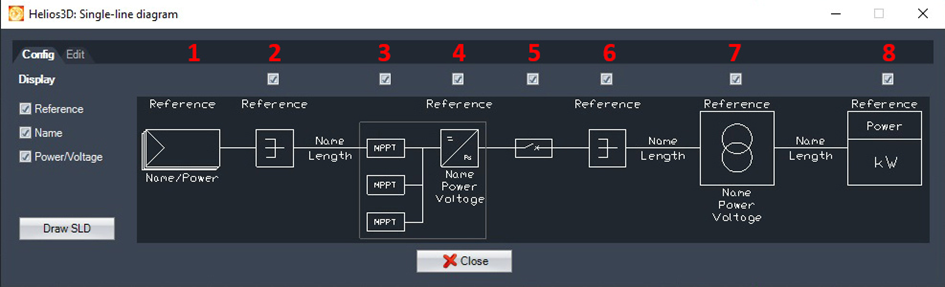
The desired parts of the SLD are toggled in the configurator.
(1) The strings are always displayed and preceded by the number. If more than 3 identical structures are found, they are summarised and thus displayed in abbreviated form. The number of collected elements appears behind the 3 vertical dots.
(2) Toggle collector or Y-connector visible/invisible.
(3) Select whether MPPTs are to be displayed or not
(4) Select Inverter
(5) Draw in disconnector
(6) Select AC collector
(7) Select transformer
(8) Select grid connection point
Creating partial extracts of an SLD
It is possible to create only parts of an SLD. To do this, select the entry in the electrical tree from which the subordinate parts are to be drawn. Here too, what is visible in the tree is drawn.
The selected part is drawn with Draw SLD or can simply be dragged and dropped. The SLD is only drawn up to the level that was selected.
Edit
The Edit tab contains functions and help tools for several areas, including functions that make it easy to create symbols in the Helios 3D symbol systematic. This makes it much easier to create the layers and elements required for a Helios 3D-compatible symbol.
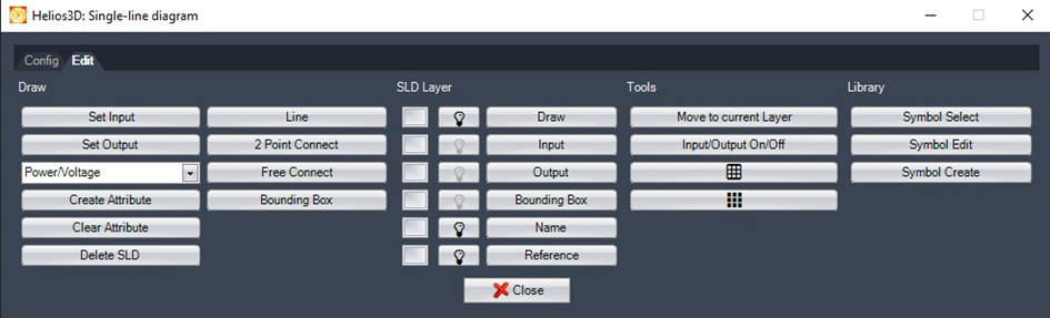
There are 4 areas:
Draw
contains functions that automatically switch to the correct layer to create certain elements of the symbol and start the corresponding drawing function.
- Set Input switches to the green input layer and enables the direct placement of input circles
- Set Output switches to the red output layer and enables the direct placement of output circles
- Use the list selection to select which type of attribute you want to draw with Create Attribute
- Clear Attribute deletes all assigned attribute contents for a selected block
- Delete SLD deletes all existing SLDs
- Line switches to the Draw Layer to draw lines for a symbol.
- 2 Point Connect creates a dynamic connecting line between an output and an input.
If the input and output are at different Y coordinates, the continuing line is changed to the required height of the input at half the X distance. If the symbols are moved, the connecting line is automatically adjusted according to this rule. - Free connect makes it easier to create right-angled connecting lines that bypass other symbols
- Bounding Box switches to the Bounding Box layer and creates a free rectangle with the line style of the Bounding Box layer.
SLD Layer
allows direct access to the layers used by the SLD symbols, to set them as the current layer or to toggle them ON or OFF. This makes it easier and faster to create your own symbols
Tools
has buttons and functions to change object layers and switch drawing aids
- Move to current Layer changes the layer of all selected objects to the layer that was selected as the current layer under SLD Layer. This allows you to quickly adapt your own symbols to the layer structure of the Helios 3D symbols.
- Input/Output On/Off switches the corresponding layers on/off for the display
- The buttons are the direct access to Grid and Snap
Library
provides direct access to the SLD symbol directories for quick access to the symbols, in order to select or draw them.
- Symbol select opens the symbol library directory to select a symbol to be inserted.
- Symbol edit allows you to select a symbol from the library directory, to open it as an independent drawing for editing or adding to.
- Symbol create opens an empty drawing with all symbol layers, if you want to create a new symbol. This must be saved in the symbol library.