Areas
Definition in General
You can create an area definition by drawing polylines in the top view or by adding an existing object (a line of the corresponding type) to the database.
In addition to the button in the “Placement” tab, all functions for adding an area definition are also available in the context menu of the structure list and the extended context menu of Autodesk Civil 3D.
Areas define the spatial boundary in which placement-related objects can be generated, organized, or evaluated in Helios 3D. They are especially relevant for tracker-based layouts, because an area can provide the geometric basis for generating tracker blocks and registering them as fields.
Use areas when you want to subdivide a project site into controlled placement zones, define the limits for tracker block generation, or prepare field creation based on a specific tracker system. The area geometry must be clean, closed, and located inside a valid Digital Terrain Model so that Helios 3D can relate the area to the terrain.
All area-defining polylines, including fields, exclusion zones, device areas, and others, must not contain self-intersections or duplicate vertices. Closing these polylines should be done using the polyline’s properties.
Before registering or using an area, check that the boundary is geometrically clean. The polyline should be closed, should not contain overlapping segments, duplicate vertices, gaps, or self-intersections, and should follow the intended project boundary precisely. Invalid or unclear boundary geometry can lead to missing fields, incomplete tracker block generation, or unexpected placement results.
If an existing CAD object is used, verify that it represents the correct boundary type and that it is located on the correct terrain. This is especially important when working with imported survey data, copied geometry, or project drawings that contain multiple terrain models.
It consists of a closed „Polyline“ or „3D Polyline“ that must be entirely contained within a Digital Terrain Model (DTM). Helios 3D automatically establishes a connection between the area and the digital terrain it resides in.
An area is not only a drawing object. After it has been added to the project database, Helios 3D can use it as a placement-related project object. This connection is important because generated tracker blocks, fields, and placement parameters depend on the registered area and its relationship to the terrain.
If the area is outside the DTM, only partly inside the DTM, or based on invalid geometry, subsequent placement steps may fail or produce incomplete results.
Properties
In the area properties, you will find parameters for generating fields based on a specific tracker system. This system defines a block of arrays/racks that together form a single tracker. You can specify a fixed number of arrays per row and a maximum number of array rows to determine the size of these blocks, which in turn defines the size of the fields being calculated.
The arrays within a row are connected by a rotation axis, while the array rows are linked by the drive shaft.
The settings configured for the area are transferred as placement parameters to any generated field.
The area properties define how tracker blocks are generated inside the selected area. These settings are used to derive field geometry and placement parameters from the selected tracker system. They should be checked before generating blocks, especially when the area is irregular, when adjustment lines are used, or when minimum distances to the area border are required.
Changes in the area properties can influence the generated block layout, the resulting fields, and the placement behavior that is transferred to those fields.
Generate Tracker Blocks

Generates tracker blocks based on the configuration provided below. The blocks are inserted as 2D polylines and can then be registered as fields.
After generation, visually inspect the inserted 2D polylines before registering them as fields. This helps ensure that the tracker blocks are positioned as expected and that the distances, row counts, border offsets, and optimization settings produce the intended layout.
Show start point for tracker blocks with mouse cursor

Position the mouse cursor at the starting point if the blocks are not generated from a suitable position. This can occur if a row adjustment line is used.
Register as Fields

Registers all tracker blocks as fields and applies the values set below as pre-configured placement parameters.
Use this step only after the generated tracker blocks have been checked. When the blocks are registered as fields, the configured placement parameters are applied to the field definitions and can become the basis for later array placement.
Delete

Removes all tracker blocks, fields, and placements.
Warning:
This command removes generated tracker blocks, fields, and placements related to the area. Before using Delete, make sure that the affected layout objects are no longer needed or that the drawing/project status has been saved appropriately.
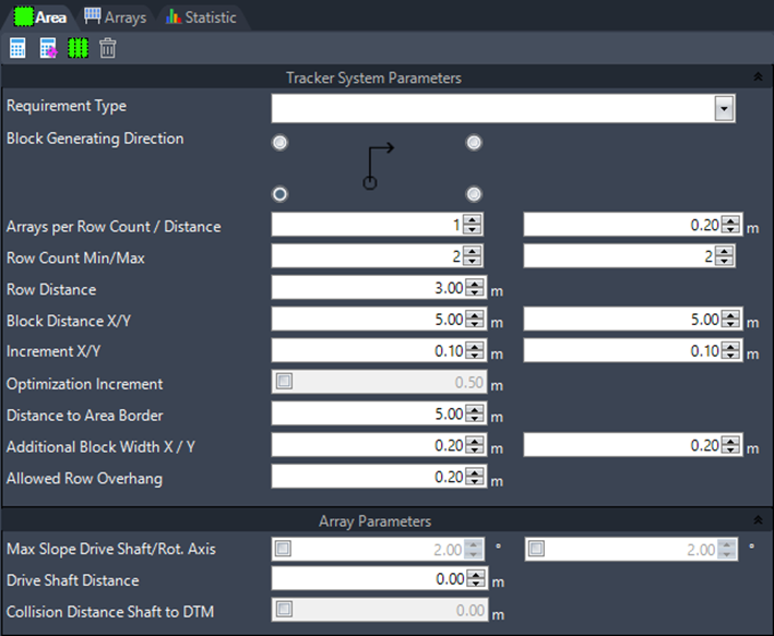
Tracker System Parameters
The following parameters control the geometry and search behavior for generating tracker blocks. They define the number of arrays, the number of rows, the distances between arrays and rows, the minimum distance to the area boundary, and the increments used when Helios 3D searches for valid block positions.
These values should match the selected tracker system, the intended PV layout concept, and the site constraints.

Requirement Type
Select the requirement type using the array selection.
Block Generating Direction
Displays the direction for generating the blocks within the area.
Arrays per Row Count
Set the number of arrays per row for the tracker block.
Array Distance
Set the distance between neighboring arrays within each row.
Row Count Min./Max.
Set the minimum and maximum number of rows to define the dimensions of the tracker blocks to be generated.
Row Distance
Set the distance between the array rows.
Block Distance X/Y
Set the distance between tracker blocks in the x- and y-directions.
Increment X/Y
Set an increment for the location detection of the tracker blocks. If the location found using the default distance settings is invalid, the tracker block will be moved in increment steps until a valid location is found.
Optimization Increment
When active, you can set an increment for the optimized generation of tracker blocks. Similar to the optimized placement of arrays, the first row of blocks will be moved northwards, and a new block layout will be calculated. The final result will include the block layout that provides the maximum area coverage.
Use optimization carefully on complex or narrow areas. A smaller increment may improve the search for a suitable layout but can increase calculation effort. A larger increment may calculate faster but can skip potentially useful positions.
Distance to Area Border
Set the minimum distance from the area border for the generation of fields.
Additional Block Width X / Y
Additional block width values can be useful when the 2D block outline must reserve extra space for the actual tracker geometry on the 3D terrain. Because the final tracker extents can differ on sloped terrain, these values should be reviewed when working with uneven surfaces or large tracker structures.
Set the value for extending the field blocks in width and height. Since the blocks are generated for a plane, the extents of the entire tracker geometry may vary when applied to the 3D surface.
- The block width is calculated as follows:
Row count x Array width + (Row count – 1) x Row distance - The block height is calculated as:
Array count x Array length + (Array count – 1) x Array distance
Allowed Row Overhang
Here, you can define the overhang value for the last array in a row.
Array Parameters for Trackers
These options are described in Section „Tracker System Parameters“, as they are also part of the field placement settings.
Typical workflow
- Draw or select a closed Polyline or 3D Polyline in top view.
- Add the object as an area definition.
- Open the area properties.
- Select the required tracker system or requirement type.
- Define the tracker block parameters, including arrays per row, row count, distances, increments, and border distance.
- Generate tracker blocks.
- Review the generated block geometry in the drawing.
- Register the tracker blocks as fields.
- Continue with field-based placement or related layout steps.
Troubleshooting
If tracker blocks are not generated as expected, first check whether the area polyline is closed, free of self-intersections, and fully located inside the Digital Terrain Model. Also verify that the selected requirement type and tracker system parameters are suitable for the area size and shape.
If blocks are generated in an unexpected position, check the block generating direction, row adjustment lines, start point behavior, block distances, and increment settings. If fields are not created correctly, review the generated tracker block geometry before using Register as Fields.