Array Placement
Under the „Array Placement“ tab, it is possible to create terrain, surfaces, fields, as well as exclusion and requirement type areas, and place solar tables on them.
The top element in the hierarchy is the terrain (DGM). All other elements, referred to as surface definitions, are subordinate to this terrain. Directly beneath the terrain are the properties or surfaces. Within these surfaces, fields can be created, where the tables are then placed.
To organize the arrangement of table rows within a field, exclusion areas and requirement type areas (each as a collection), as well as an alignment line for the rows and a starting point, can be defined.
When placing, a collection of table rows is created, under which the individual rows are listed in order. Each row, in turn, contains a numbered list of the tables placed on it.
The following graphic shows the placement tab of the Helios palette with an example of the described structure.
In addition to the placement options, the tool also offers functions for calculating external shading. Shadow objects, meaning objects that cast shadows on the terrain and possibly on solar tables, can be inserted into the drawing. For each of these shadow objects, the shadow projection on the terrain can then be calculated. All shadow objects are organized into a collection and attached to the drawing, as illustrated in the following graphic.
Using the symbol in front of a shadow object, you have the option to thaw or freeze all calculated shadows with one click. Since multiple layers are grouped together, a mixed – symbol will be displayed if the status is not clearly defined.
Buttons of Structure List
New

Here you can add selected polylines or lines as area definition or draw one of them as an area definition like displayed below.
You can directly create areas, fields, exclusion zones, requirement zones, adjustment lines, or split lines by drawing them, or by adding an existing polyline or line (applicable only to start point adjustment lines) to the database. Additionally, you can register objects as shadow objects or insert predefined shadow objects such as „Tree,“ „Bush,“ „Trunk/Pillar,“ „Block,“ or „House.“
Delete Area Definition

Deletes an area definition from the database and shows a request whether the object should also be deleted from the drawing.
Move Up/Down

Move entry upwards. This allows resorting the entries e.g., the order of displayed fields.

Move entry downwards. This allows resorting the entries e.g., the order of displayed fields.
Zoom to Object

Zooms into the drawing until the selected object completely fills the screen.
Insert Label

Label selected entry. By that, a text object with the entry name will be added to your mouse cursor for insertion into the drawing.
Select in Tree

When you select an object in the drawing it will automatically get selected (marked) in the structure tree.
Placement Tree Context Menu
The context menu of the structure list is shown below for two different situations. On the left, a field is selected, and on the right, a shadow object is selected. Please note that the commands listed in the menu may vary depending on the current selection.
Add & Draw


The submenus under these options are identical to those of the <Add Area Definition> button. They allow you to either add existing CAD objects to register them in HELIOS 3D or draw new objects, which are automatically registered.
Rename

Renames the selected entry.
Delete

Deletes all selected objects.
Apply “Project” sun date

Replaces the sun data of the selected fields with the settings specified on the “Project” page.
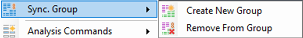
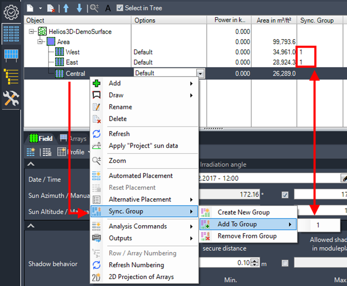
Sync. Group

The only addition is the synchronize fields in groups option, which allows array rows to seamlessly continue across all fields within the same group, treating them as one large field. The procedure for the command shown below is explained in Section „Synchronization Groups for Fields“.
Automated Placement

Automatically locates a starting point for the placement of the first row. The initial array is positioned at the southernmost edge of the field, with each row placed from left to right. This direction can be reversed by selecting the “Place Right-Aligned” option in the placement settings.
Reset Placement

Resets the placement configuration for all selected fields.
Refresh

Refreshes the structure list.
Synchronization Groups for Fields
Multiple fields can be grouped by assigning them a group number, which is displayed in the “Sync. Group” column of the placement tree. The group number indicates which fields are linked, ensuring that placement commands consistently update the layout for all fields within the same group.
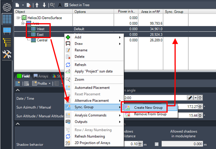
Certain placement options can still be customized for individual fields, provided they do not conflict with one another. You can add more fields to an existing synchronization group at any time or create a new group as needed.
When placement is initiated with a field from any synchronization group selected, the layouts of all fields within that group are updated automatically.