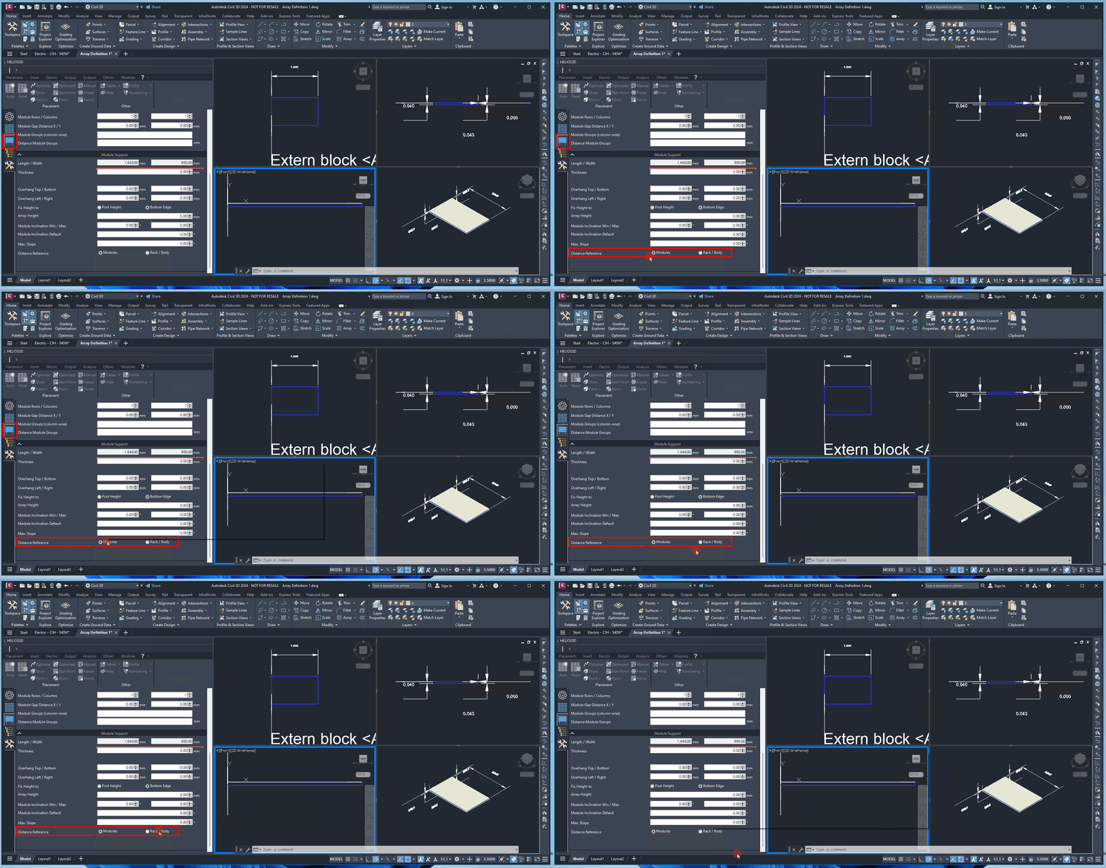
Module Support
Length/Width
These measurement data are calculated based on the arrangement of the modules, their gap distances, and the overhang values specified below.
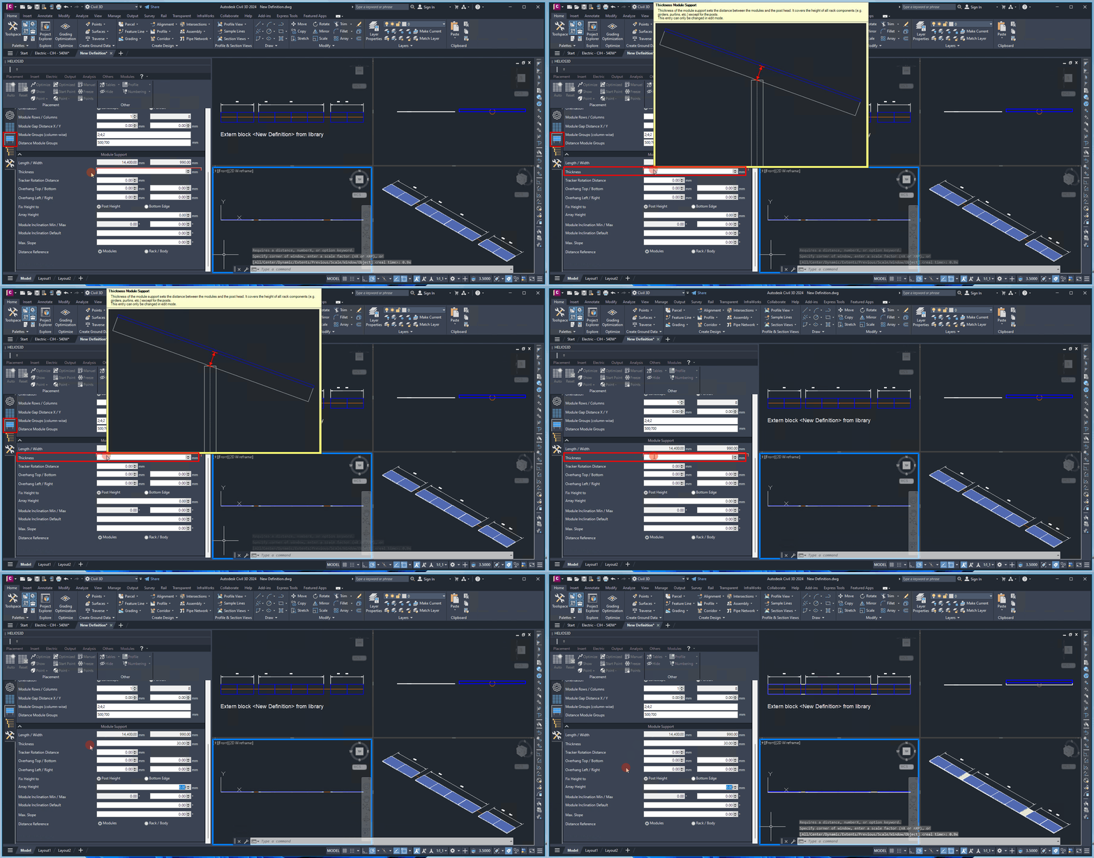
Thickness
Thickness of the Module Support. This value represents the height of all rack components (e.g., girders, purlins, etc.), excluding the posts. This field can only be modified in edit mode.
Just for single-axis- and multi-row trackers
For single-axis trackers, certain presets are applied to the array definition, and the „Rotation Distance“ option becomes active. For example, the array height is determined by the post height, and there is only one row of posts.
For trackers, the table body (highlighted in red) is always generated with no module tilt (0° inclination). The row distances are measured from table body to table body.
Tracker Rotation Distance
The Rotation Distance defines the position of the rotation point, measured as the distance from the post head for cases where the module has a non-zero inclination angle.
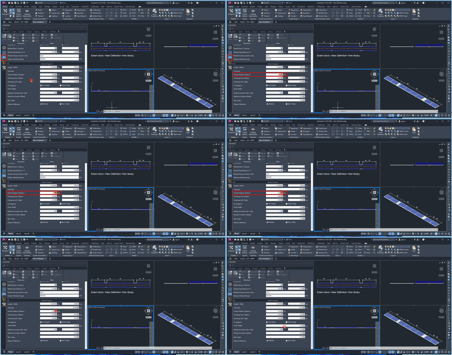
A value of 0.00 mm means that the modules rotate directly around the post head.
The maximum rotation distance is determined by adding the module support thickness to the module depth.
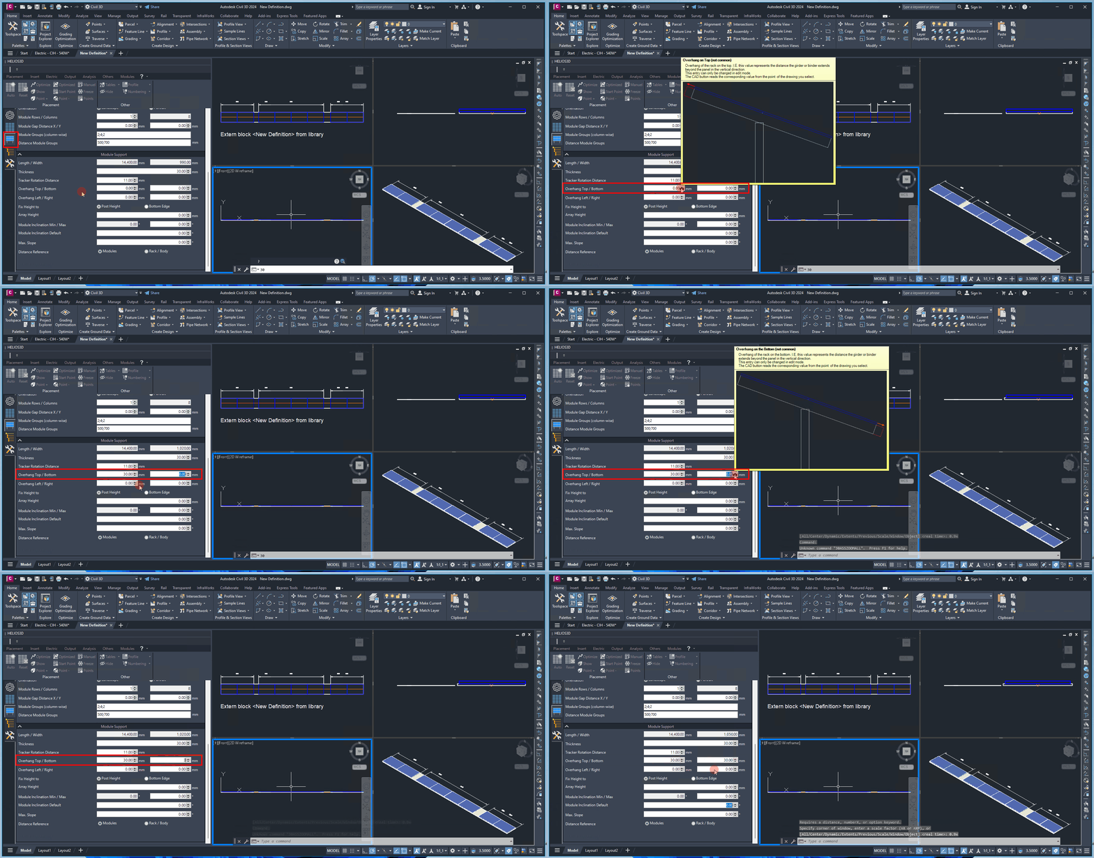
Overhang Top/Bottom
Here, you can enter the distance that the girders or binders extend beyond the module in the vertical direction (though this is not typical).
This measurement increases the total area required for an array, in addition to the area defined by the modules. These components must be taken into account when calculating shadows and the distances between rows and arrays within a row.
Overhang Left/Right
Here, you can enter the distance that the purlins extend beyond the module in the horizontal direction.
This measurement increases the total area required for an array, in addition to the area defined by the modules. These components must be considered when calculating shadows and the distances between rows and arrays within a row.
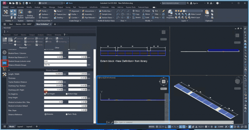
Fix Height To
The array height can be defined either by a fixed post height or by a fixed front edge height.
Post Height:
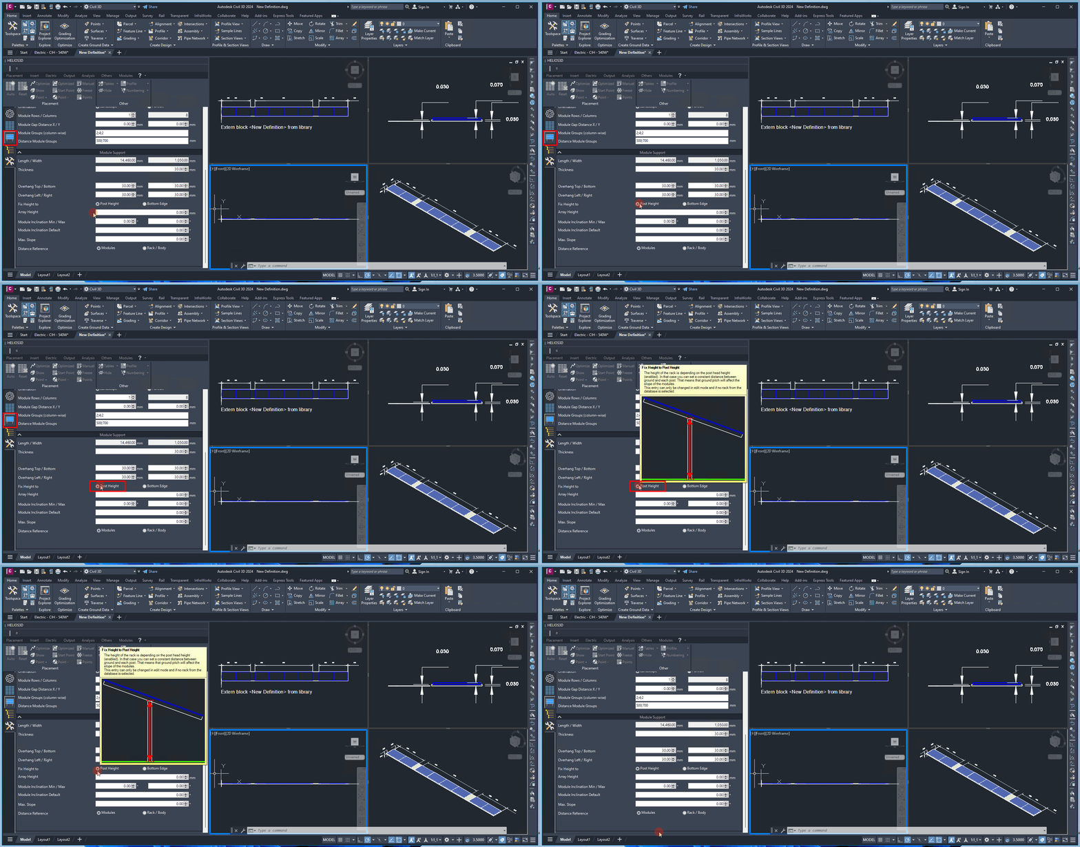
Front edge height: (measured from the photovoltaic active area)
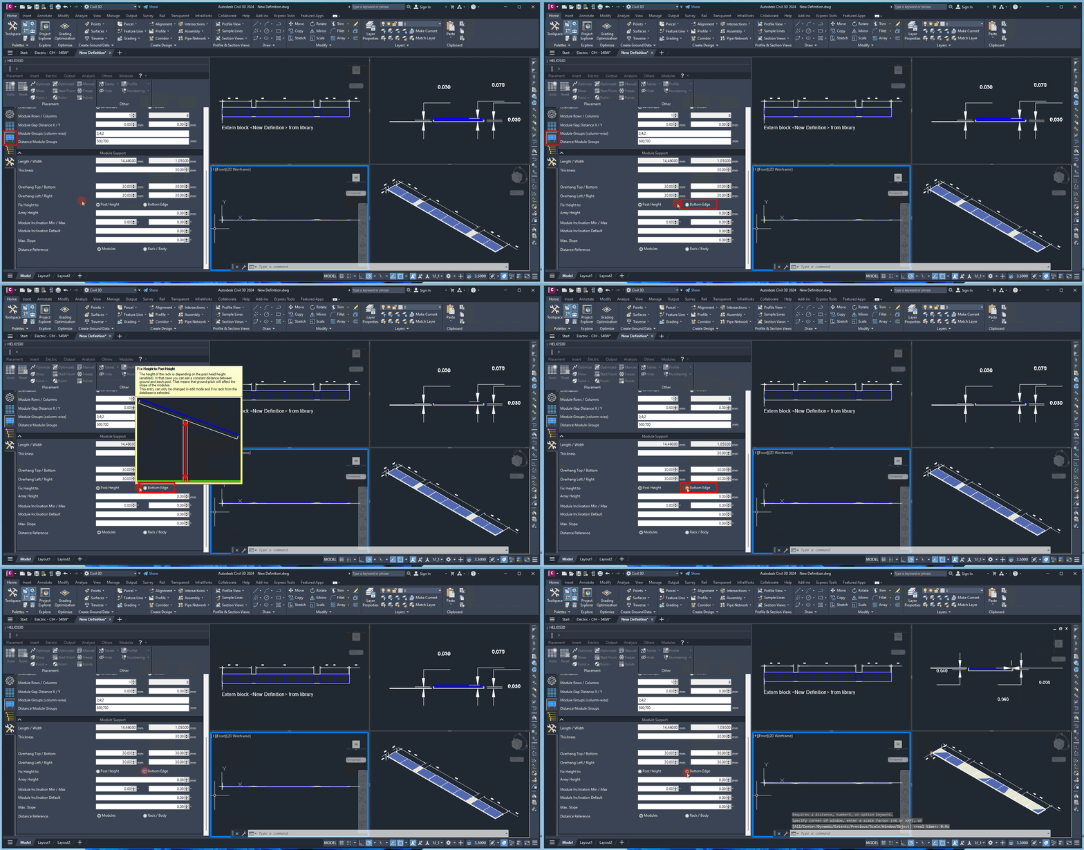
Array Height
The „height“ value for the array specifies either the post height or the height of the front edge.
Module Inclination Min/Max (degree)
The angle range to which the modules can be adjusted on the rack serves as a reference in the project. This enables Helios 3D to detect any exceedance of technical limits.
Module Inclination Default (degree)
The default module inclination value is used to define the geometry displayed in the table definition drawing and serves as a reference for post settings.
The post distance settings are based on this inclination angle and will adjust accordingly for other angles.
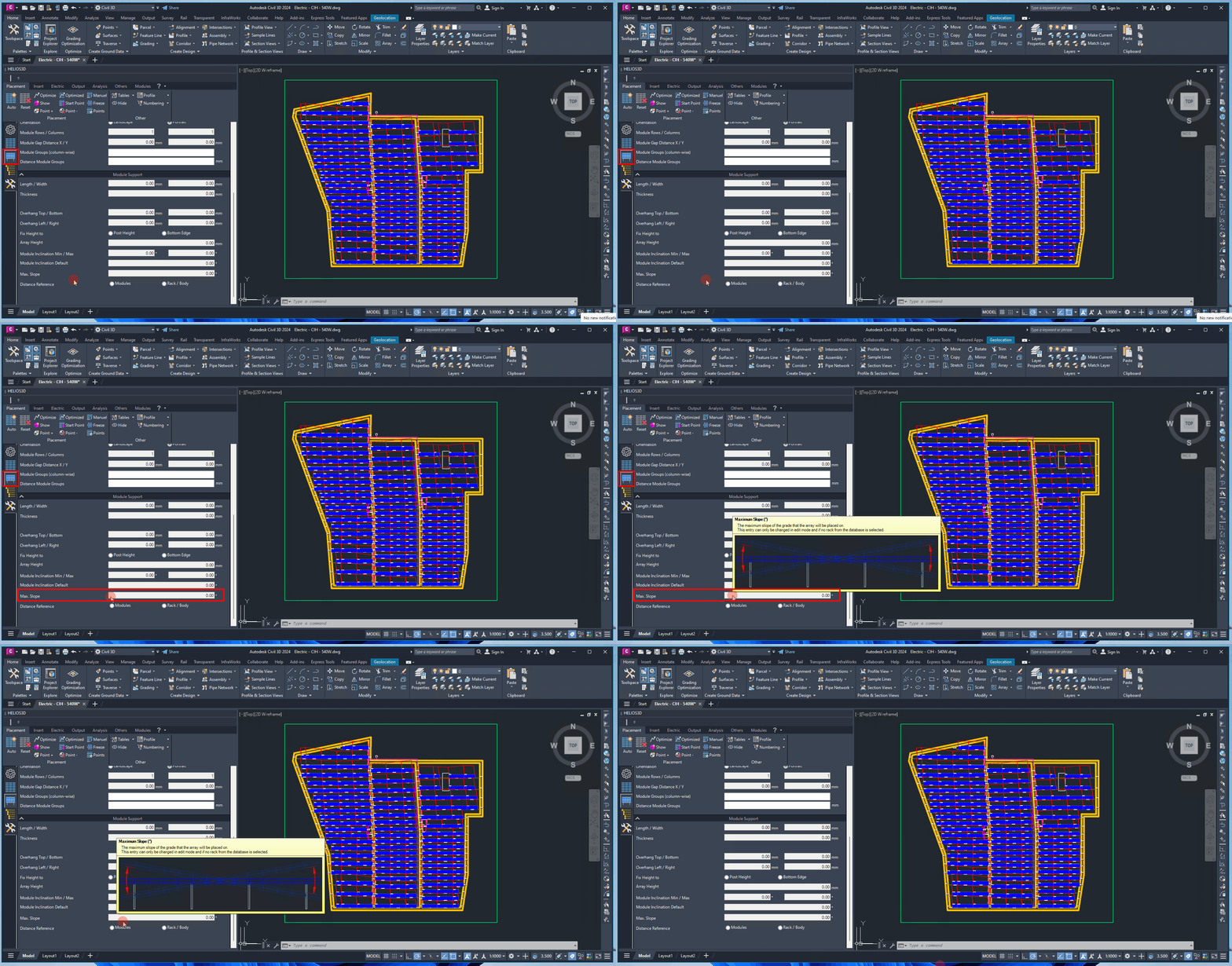
Max. Slope (degree)
For structural stability, racks can only be installed on slopes within a limited range. Here, you can specify the maximum allowable slope of the ground on which the rack will be placed.
Distance Reference (at Slope)
The sloped distance between two racks can be measured relative to either the array surface or the rack itself (with a <Floor> option coming soon). This distance considers the modules and may account for the overhang specified in the “General” tab, which will deactivate the “Overhang Left/Right” input fields.
When the reference is set to “Rack,” the distance is also verified at the bottom, which is necessary for configurations such as racks without posts.
