Others
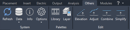
Command Group System
Refresh Data

This function reloads all data from the drawing and the database, ensuring that all internal objects are updated. It also attempts to resolve communication issues between Helios 3D and Autodesk Civil 3D, which can arise due to problems such as uncaught exceptions, potentially causing commands to malfunction.
Data exchange between DWG and database
The local article data in a drawing may not match the corresponding records in the database, for example, if a DWG file has been copied to another HELIOS 3D installation.
The import/export commands offer two options:
- Read all data from the database and overwrite the local data in the drawing.
- Overwrite the database records with the local data from the current DWG file.
Import article data from database
Imports the information for any article used in the local DWG file and overwrites the DWG information permanently. Afterward, any new table placements, electrical placements, or other actions will use the updated local article data.
Export article data to database
Exports all local articles from the DWG to the database. Existing records in the database will be replaced.
Info

This function is for informational purposes only and has no additional functionality. It provides quick access to details about the current system, which can be useful when seeking support.
| No settings can be changed in this section! To make any changes, please go to the database. You will need the appropriate access rights to modify any settings there. |
Program / Database
This section displays the version numbers of both the program and the database.
Program Language
This section shows the language of your installation.
Program Directory
This section displays the full program path of your installation.
Drawing Filename
This section displays the full folder path of the current drawing.
Project No./Name
This section displays the number and name of the project associated with the current drawing.
Drawing No./Name
This section displays the number and name of the current drawing.
Server / Database
This section displays the name of the database and the server where it is located.
User Name / Password
Here you can see the username and the encrypted password you used for database login.
System Settings
The following figure illustrates the settings for the currently active system. A detailed explanation of these system settings is provided in section „System Settings“.
User Data
This dialog displays the data of the user currently connected to the database, as shown below. This information corresponds to the data in the User Management section of the database application. A detailed description of User Management can be found in section „User Management“.
Options
Here, you can toggle between various display options and enable features like RollOver tips or the radial menu. Changes made in this section temporarily override system or user settings. These adjustments are not saved; upon restart, Helios will revert to the original values from the corresponding default settings (e.g., user settings).

Show AutoCAD / Helios3D RollOver Tips

When active, the AutoCAD RollOver tip is replaced for objects that are registered with HELIOS 3D.
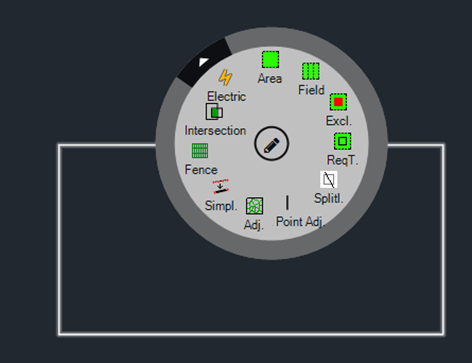
Show Radial Menu
When active, a radial menu can be accessed by pressing the “Alt” key while hovering over an AutoCAD object that contains functions for quick access. This behavior is similar to the RollOver tip, but combined with the “Alt” key.
For the default setting, please refer to section „User Management“.
Command Group Palettes
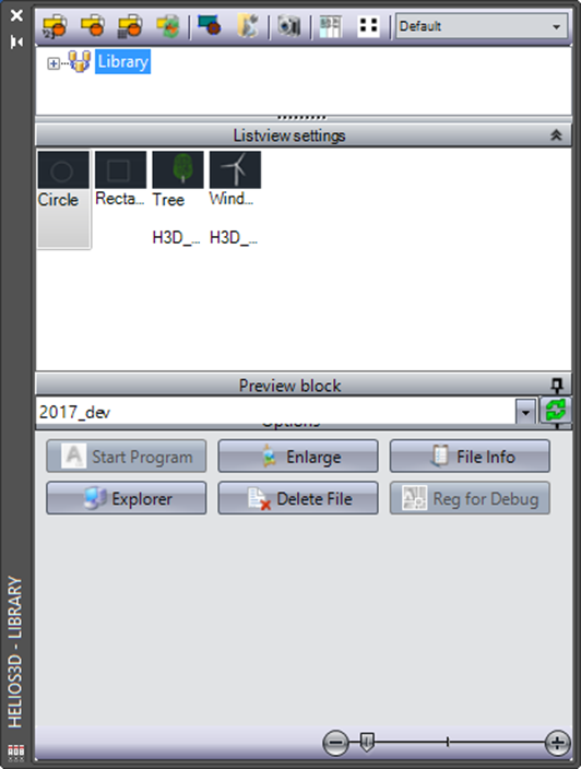
Open Library

The Block Library is a tool for managing and inserting predefined blocks into a Autodesk Civil 3D drawing. These blocks can serve as placeholders, which are later replaced by objects with specific properties for web browser export.
Insert block multiple times

This places the block at the mouse cursor, allowing it to be inserted multiple times by left-clicking.
Insert block once

This places the block at the mouse cursor, allowing it to be inserted with a left click. After the first insertion, the action is completed.
Insert block in row

This allows inserting the block using an insertion pattern (via the Autodesk Civil 3D „row“ command). The first left-click inserts the initial block, followed by three options in the Autodesk Civil 3D command line and context menu, as displayed below.
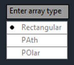
- Rectangular: Inserts the block in a rectangular pattern.
- Path: Inserts the block along a defined path, which can be an existing object, such as a polyline.
- Polar: Inserts the block in a circular pattern, starting from the location of the first click, with the center of the circle defined by the second click.
Change block

Replaces the block selected in the drawing with the block selected in the library palette.
Create block (wblock)

Creates a new block (using the Autodesk Civil 3D „wblock“ command) from the selected objects and adds it to the chosen library entry.
Open block as document

Opens the drawing of an external block, including information about the DWG file.
Show block list in detail mode

Shows the block list in detail mode
Show block list in preview mode

Displays the block list with a preview image.
Open Layer Manager

The Layer Manager can be used to freeze or thaw layers that contain the HELIOS 3D objects listed. If multiple exclusion zones are assigned to different layers, all these layers can be switched simultaneously.

Thaw All

Thaws all layers that contain registered objects.
Freeze All

Freezes all layers that contain registered objects.
Refresh

Refreshes the list.
Display Order by Layer

This button activates the AutoCAD command <AecLayerOrder>, which opens a dialog box allowing you to organize the display order of drawing entities based on their insertion layers.
It is particularly helpful for prioritizing Helios3D markers, such as those indicating DTM collisions or slope conflicts, by displaying them above all other drawing elements.
Command Group Edit
Set Elevation for Lines

To create a DTM (Digital Terrain Model) from polylines, all polylines must be assigned the corresponding z-coordinate (height). This function offers a convenient method for setting the height of each line.
You can enter a start height and a step width, both in meters. The command line will prompt you to enter these values. Afterward, you can select the lines one by one, starting with the line that should be set to the start height. The height will be applied incrementally based on the step width.

Adjust Line to Surface
You can lift one or more polylines to match the height of the terrain. This function automatically adds a definition point to the resulting polyline whenever a line segment intersects a terrain triangle, ensuring that the resulting polyline fully aligns with the surface of the terrain.
To reduce the number of definition points in the resulting line to the minimum required, please use the function, which is described in the following section.
Combine Lines

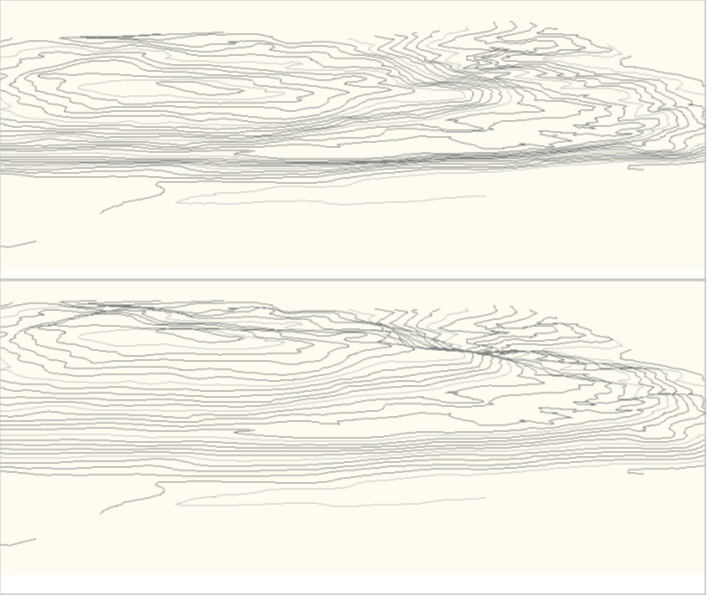
Some drawings may contain contour line segments that are not connected as a single polyline. This function allows you to combine line segments of the AutoCAD type LINE into a polyline. For this to work, the endpoint of line A must coincide with the endpoint of line B.
When using this function, the command line will first prompt you to select the lines. Afterward, you will be asked to enter the minimum segment length. In the final step, the function can reduce the number of polyline segments by removing any segments shorter than the specified minimum length.
| Please note that only lines with the same direction can be combined. Specifically, a start point can only be combined with an endpoint, and an endpoint can only be combined with a start point. It is not possible to combine a start point with another start point, or an endpoint with another endpoint. |
Simplify

This function automatically eliminates a definition point from a polyline if a straight line drawn from the last definition point to the next definition point passes through the current definition point in 2D.
By using this function, you can reduce the number of points in the polyline, which in turn decreases the number of calculation steps required for other Helios operations.
| Please note that the simplification is calculated in 2D, meaning the heights (z-coordinates) will be disregarded during this process. You should take this into account when using the polyline later, as the height information will be lost. |