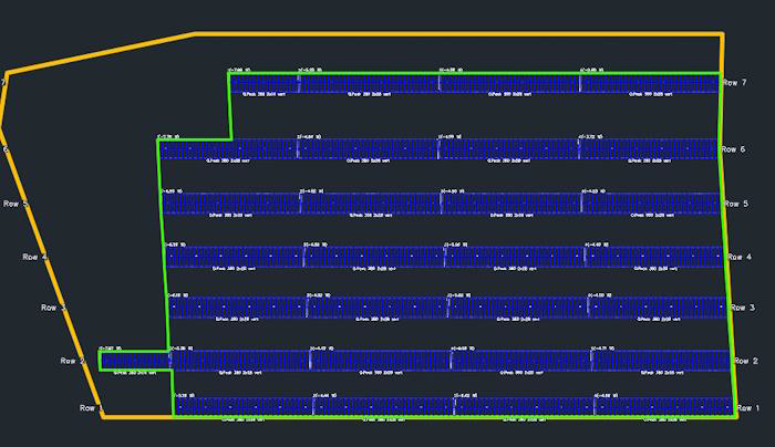
Placement Results
Placement Statistic
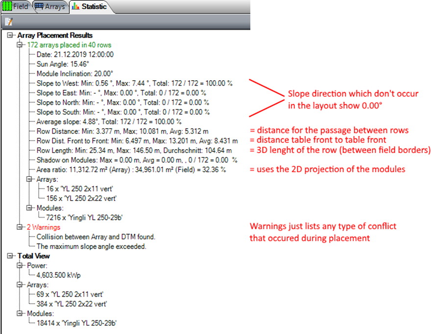
The following picture shows the contents of the statistics.
Row Distance Standard Table
The row distances are measured between the table bodies. At the table front, the front edge of the modules is used for tables without overhang, and the front edge of the module support is used for tables with overhang. At the table back, the body always ends at the upper edge of the module support, which aligns with the back edge of the modules for tables without overhang.
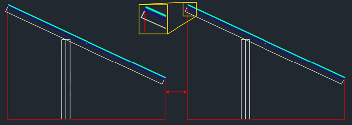
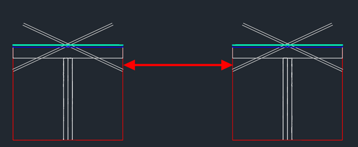
For the passage between two table rows, which is shown as row distance in the placement statistics, the measurement from table to table follows the examples below.
Without overhang:
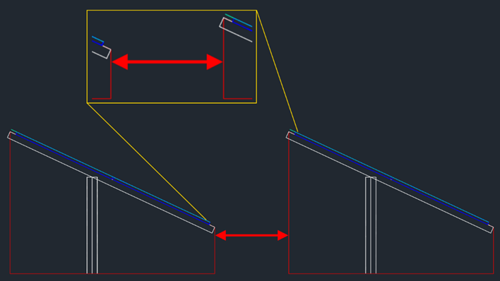
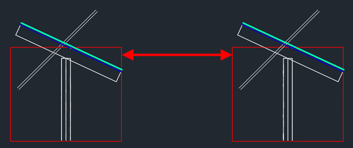
With overhang:
Row Distance Tracker Table
The distance between tracker rows is measured between the bodies (red), with the bodies always generated for a module inclination angle of 0°.
If the tracker is placed with a module inclination different from 0°, only the module position changes, but the table body and row distance remain unaffected.
Single Axis Tracker Example
The example in this section describes the general use of a single-axis tracker in Helios 3D. Please note that this description represents just one possible scenario, and other configurations might also lead to sufficient solutions!
Generally, trackers can be used in the same way as all other types of arrays. The key difference is that the insertion line for an array row aligns with the post line at the center of each array (rotation axis), whereas other array types have the insertion line at the front edge of each array (block).
There are no inherent relationships between tracker arrays, so this function does not recognize connections between arrays that belong to the same tracker (control unit). Each array remains an individual array, meaning any special grouping must be handled through the placement properties.
One option is to separate your placement area into several fields, each corresponding to the size of a tracker. The description below illustrates a possible procedure for working with a single field.
Placement procedure for a single field:
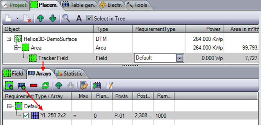
- First, you need to select your field and assign a tracker array.
- In contrast to other array types, the module inclination for placement should be set to „0.00“, although any angle can be set, similar to arrays with a fixed module inclination. The maximum rotation will be displayed as polylines during placement, but the modules will appear with the set inclination angle.
The row direction should be changed to „North-South-Placement“ to allow the module orientation to be rotated between east and west.
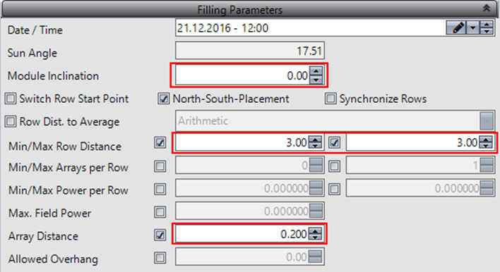
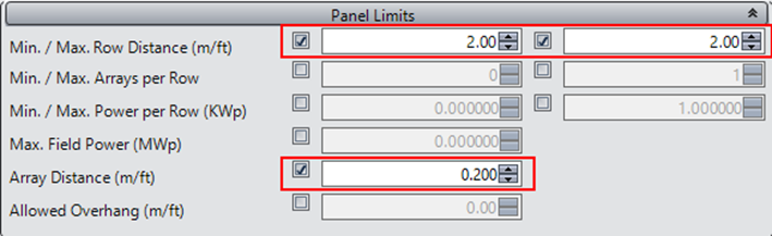
- In the „Panel Limits,“ a fixed row distance should be set to an appropriate value, and the distance between arrays within a row should be specified. Additional distances between arrays of different trackers will need to be configured later.
- Grouping arrays according to their association with the same tracker can be achieved in different ways, depending on the field structure.
In a rectangular field, „Array Groups“ can be used to create gaps between arrays within any row.

- For non-rectangular fields, you can try using array groups in combination with start point adjustment lines, or you can group the arrays manually by adding exclusion zones.
To add extra distance between array rows belonging to different trackers, exclusion zones are the only solution.
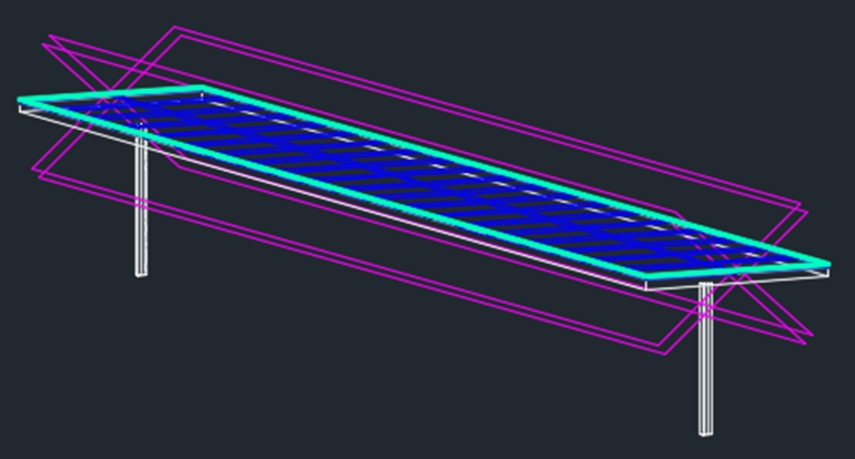
The result of that procedure looks like this:
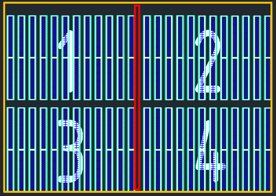
One tracker array consists of the modules and panel area (an abstract display of the rack structure), the posts, and the maximum rotation to each side. The maximum rotation is displayed by the magenta-colored polylines in the next figure, representing the upper plane of the modules and the lower plane (bottom) of the panel.
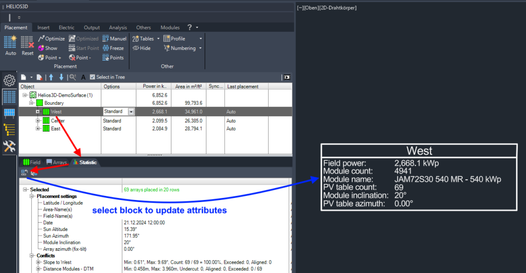
Attributes
Attributes have been added to the placement statistics in the table design.
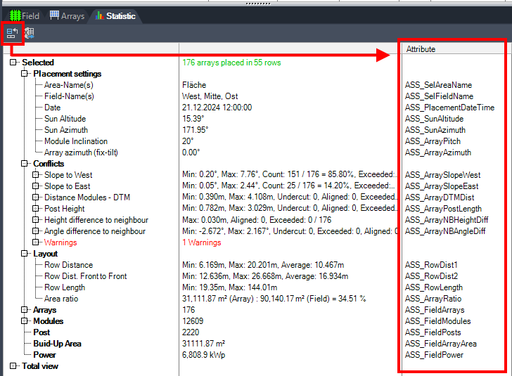
You can create your own blocks with these attributes for insertion into any DWG file. The button on the statistics page populates or updates the values.

You can first select one or more blocks in the drawing whose attributes you want to update with the data from the statistics page. The attribute names are listed in the third column of the statistics.
If a matching attribute is found in a block, it will be updated with the corresponding value from the second column of the statistics.
If an attribute appears multiple times in the statistics list (e.g., for tables), only the first occurrence will be updated.
For example, if you need data for a specific table, you can select the corresponding table node in the statistics and use the attribute command via the context menu. In this case, only the selected node and its sub-nodes will be matched.
Example Procedure:
Two examples can be found in the main installation folder under „Samples“ (e.g., C:\Helios3D\Samples). The DWG files can be used directly, and the XML files can be imported into the HELIOS3D Library.
To import the examples into the library, follow these steps:
- Open the Library Palette.
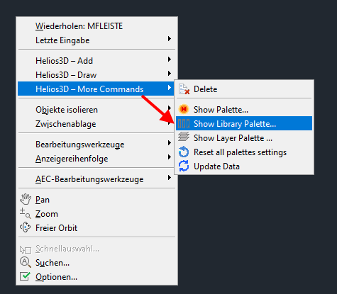
- Right-click on the library tree and select “Import…”.
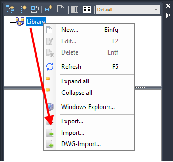
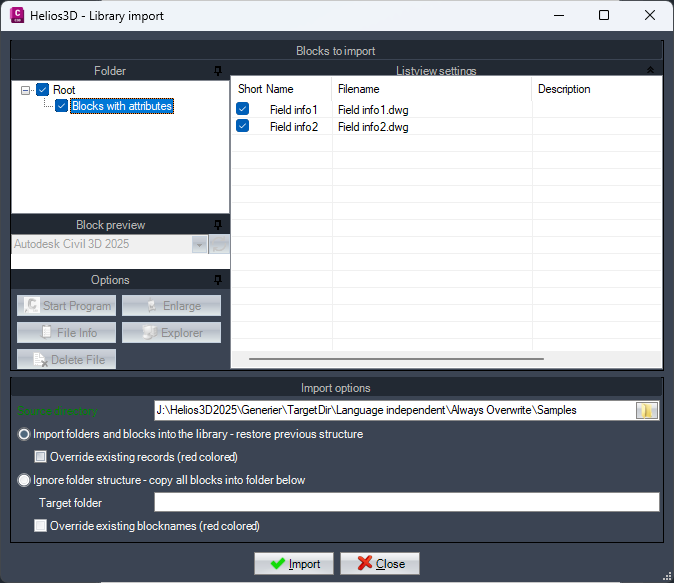
- Select the “Samples” folder.
- Choose the data you want to import. The sample data includes the folder “Blocks with attributes” and two examples demonstrating field information (Field info1, Field info2).
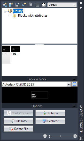
- The samples will be displayed in the library and can be used like any other blocks, for example, when adding your own shadow objects to the library.
- Add the block “Field info2” to your drawing.
- Select a single field (or a group of fields) and click the “Assign Attributes” command on the Statistics page.
- When you select the block that contains the attributes, the values from the selection in the previous step will be displayed.
2D Polyline – net placement area
Creates a 2D polyline as a polygon around the tables, describing the net usable area.
While the placement statistics indicate the usable area and area coverage based on the field boundary, this polyline can be used by the user to calculate the net area.