Yield Assesment

This opens the dialog for yield assessment for the current layout, displaying the parameters and device values used to calculate the total yield over the course of a year.
This function allows you to compare different layouts and identify the yield-optimized configuration.
This command calculates the annual yield for your layout. Weather data can be retrieved online from the Meteonorm database or imported from a weather data file.
Additional parameters, such as shading effects, electrical settings, or general parameters, can be configured in various sections.
- The main settings for the calculation are defined in the “Calculation Parameters” tab.
- The “Electric Parameters” tab allows you to input missing values for modules and inverters.
- The “Fields” tab lets you select specific fields to include in the calculation.
To provide a clearer overview, we will now revisit and describe the different sections in more detail.
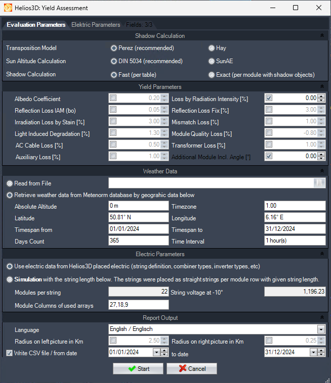
Calculation Parameters
Shadow Calculation
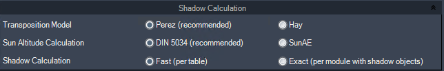
Algorithm for the Transposition Model
Here, you can choose the transposition model for calculating irradiation. The Perez model is recommended for its higher accuracy, and it aligns with the default settings in PVsyst version 6.x. The Hay model, on the other hand, is considered more classic and robust.
Algorithm for Sun Altitude Calculation
This option allows you to select the method for calculating the sun’s altitude. You can choose between the DIN 5034 method or the SunAE algorithm for the calculation.
Calculation Parameters
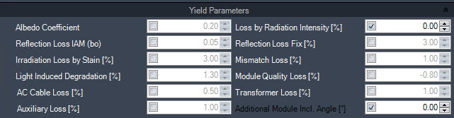
Albedo Coefficient
Enter the albedo value (reflectivity of the surface) for the calculation.
Insert Loss by Radiation Intensity in %
Enter the percentage of PV loss due to radiation intensity variations.
Insert Reflection Loss IAM
Insert the reflection loss factor related to the Incident Angle Modifier (IAM).
Insert Reflection Loss Fix in %
Enter the fixed reflection loss percentage.
Insert Irradiation Loss by Stain in %
Insert the percentage of irradiation loss caused by stains or dirt on the modules.
Insert Mismatch Loss in %
Enter the percentage of loss due to module mismatch.
Insert Light Induced Degradation (LID) in %
Insert the LID loss factor in %. This value is typically provided by manufacturers of crystalline modules.
Insert Module Quality Loss in %
Insert the quality loss percentage for the modules. This factor applies to the power (Pmpp) in all calculations and serves as a correction factor for the manufacturer’s data.
Insert AC-Cable Loss in %
Insert the percentage of AC cable loss.
Insert Transformer Loss in %
Enter the percentage of loss in the transformer.
Insert Auxiliary Loss in %
Insert the percentage of auxiliary losses in the system.
Insert Additional Module Inclination Angle
Enter the additional module inclination angle for the calculation.
Weather Data
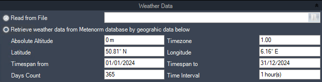
Read from File
This option allows you to import weather data from a file. Supported formats include:
- .dat files from Meteonorm or PVsyst
- TMY-3 files
Retrieve Weather Data from Meteonorm Database by Geographic Data Below
This option retrieves weather data online from the Meteonorm database based on the geographic information provided.
Absolute Altitude
Displays the absolute altitude value, which is set in the „Project“ tab of the main palette. This value significantly affects temperature influences on the system.
Latitude / Longitude
Shows the geographic coordinates (latitude and longitude) for the weather data being used.
Timespan from / to
Displays the time range covered by the weather data.
Days Count
Indicates the total number of days included in the weather data file.
Time Interval
Shows the time interval between data points in the weather data file.
Electric Parameters
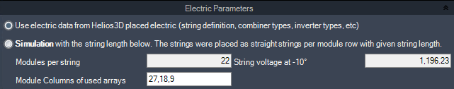
Use Electric Data from Helios 3D
This option utilizes the electrical connections and devices from the Helios 3D model for yield assessment, integrating the system’s electrical parameters into the calculation.
Simulation with the Values Below
This section allows you to configure a fictive string layout for simulation. The layout is created by grouping every xx rows of yy arrays to form a single string.
Modules per String
Enter the number of rows in a single array for each module string.
Arrays per String
Insert the number of strings that should be connected to a combiner box.
Combiner Input Count
Insert the number of strings that will be connected to each combiner box.
Inverter Input Count
Insert the number of combiner boxes that will be connected to each inverter.
Report Output
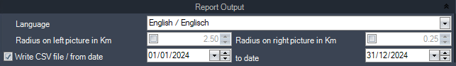
Select Language
Choose between English or German for the generated report.
Radius on Left/Right Picture in Km
The report will display two maps of the area. You can set the radius to define one map for a close-up view and another for a broader, higher-view map showing an extended vicinity.
Write CSV File
You can export the detailed weather calculation results for the selected period to a CSV file. This file can be opened in Excel or imported into other software for further analysis.
Electric Parameters
On this tab, you can enter missing data for modules and inverters, which is necessary to complete the yield assessment.
| Mandatory inputs are highlighted in bold letters! |
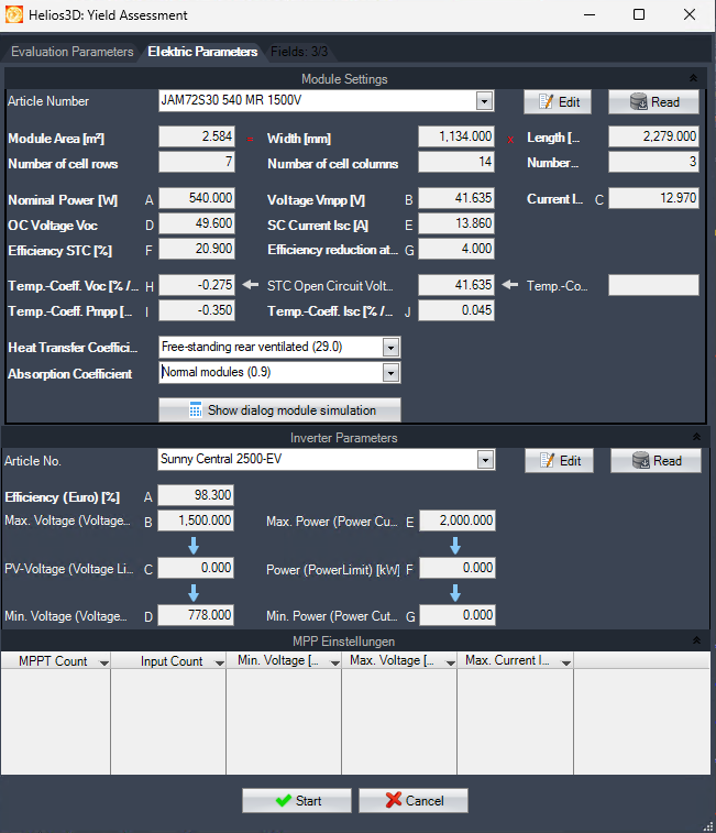
To provide a clearer overview, we will describe the sections for module and inverter parameters in two separate subsections.
Module Parameters
The module parameters listed below are mandatory. However, the „STC open circuit voltage Voc“ and the „Temperature Coefficient Voc“ are optional. This is because the „Temperature Coefficient Voc“ may not be included in some datasheets, in which case it can be calculated using the optional parameters.

Article Number
Select the module component for setting the parameters below.
Edit
Calling a dialog to edit the module data and save it in the database.
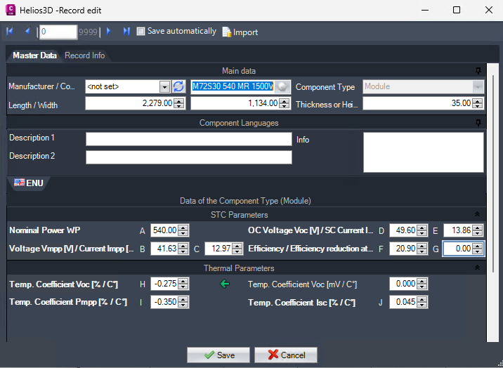
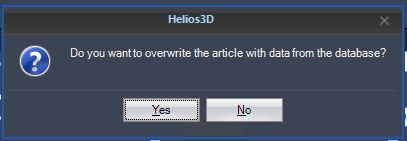
Read
Reads the article data from the database. A prompt will appear asking whether the article should be overwritten with the data from the database.
Nominal Power in W
Insert the nominal power Pmpp in watts (W).
Voltage Vmpp in V
Insert the voltage Vmpp in volts (V).
Current Impp in A
Insert the current Impp in amperes (A).
STC Open Circuit Voltage Voc [V]
Insert the STC open circuit voltage. This value is needed to calculate the temperature coefficient Voc in %, if it is not provided in the datasheet.
Short Circuit Current Isc [A]
Insert the short circuit current Isc in amperes (A).
Efficiency STC in %
Insert the efficiency STC in percentage (%).
Efficiency Reduction at <= 200W/m² [%]
Set the efficiency reduction in percentage that occurs at an irradiance of <= 200W/m².
Temperature Coefficient of Voc in %
Insert the temperature coefficient of Voc in %. If this value is not listed in the datasheet, it can be calculated from the STC Open Circuit Voltage Voc and Temperature Coefficient Voc values.
Temperature Coefficient Voc [mV/°C]
Insert the temperature coefficient of Voc in millivolts per degree Celsius (mV/°C). This is needed to calculate the temperature coefficient Voc in % if not provided in the datasheet.
Temperature Coefficient of Pmpp in %
Insert the temperature coefficient of Pmpp in percentage (%).
Temperature Coefficient Isc [%/°C]
Insert the temperature coefficient of Isc in percentage per degree Celsius (%/°C).
Heat Transfer Coefficient (W/m²·K)
Select the heat transfer coefficient of the module in watts per square meter per Kelvin (W/m²·K). Typically, this value is not listed in datasheets, but you can select between 29.0 (for rear ventilated modules) and 20.0 (for non-rear ventilated modules).
Absorption Coefficient
Insert the absorption coefficient. This is often not listed in datasheets, and you can select between 0.9 (default) and 0.8 (for very dark modules).
Module Area [m²]
The module area will be calculated based on the width and length from the datasheet.
Width [mm]
Insert the width of the module from the product datasheet in millimeters (mm).
Length [mm]
Insert the length of the module from the product datasheet in millimeters (mm).
Number of Cell Rows
The number of cell rows is automatically calculated based on the module dimensions and cannot be manually adjusted.
Number of Cell Columns
The number of cell columns is also automatically calculated based on the module dimensions and cannot be manually adjusted.
Number of Substrings
This value is always 3 and cannot be changed manually.
Inverter Parameters
For the inverter, the only mandatory parameter listed below is the efficiency. All other inputs are optional. However, if any value is missing, HELIOS 3D will skip the calculation of the related effect on the yield.
In the final report, values that could not be calculated will be listed but shown in gray.
Article Number
Select the inverter component for setting the parameters listed below.
Edit
Calling a dialog to edit the inverter data and save it in the database.
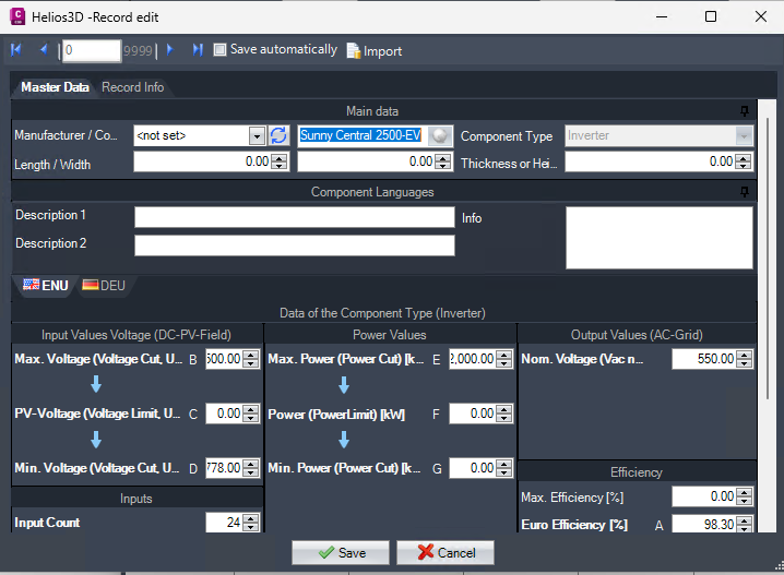
Read
Reads the article data from the database. A prompt will appear asking whether the article should be overwritten with the data from the database.
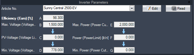
Efficiency (Euro) in %
Insert the efficiency (Euro) in percentage (%).
Max. Voltage (Voltage Cut, Vdc MPP max) [V] (optional)
Insert the maximum MPP voltage (Voltage Cut). If the voltage exceeds this value, the inverter will be disabled for safety reasons.
This value will be considered in the yield assessment if it is set.
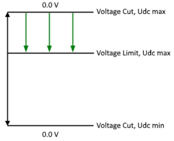
PV-Voltage (Voltage Limit, Udc max) [V] (optional)
Insert the maximum PV voltage (Voltage Limit). If the voltage exceeds this limit but does not reach the Voltage Cut, the voltage will be reduced to the set limit (as shown in the figure for Voltage Cut max).
This value is considered for the yield assessment if it is set.
Min. Voltage (Voltage Cut, Udc MPP nom) [V] (optional)
Insert the minimum MPP voltage (Voltage Cut). If the voltage falls below this value, the inverter will not be active (as shown in the figure for Voltage Cut max).
This value is considered for the yield assessment if it is set.
Max. Power (Power Cut) [kW] (optional)
Insert the maximum power (Power Cut). If this power limit is exceeded, the inverter will be disabled for safety reasons.
This value is considered for the yield assessment if it is set.

Power (Power Limit) [kW] (optional)
Insert the maximum PV power (Power Limit). If the power exceeds this limit but does not reach the Power Cut, the power will be reduced to the set limit (as shown in the figure for Power Cut max).
This value is considered for the yield assessment if it is set.
Min. Power (Power Cut) [kW] (optional)
Insert the minimum power (Power Cut). If the power falls below this value, the inverter will not be active (as shown in the figure for Power Cut max).
This value is considered for the yield assessment if it is set.
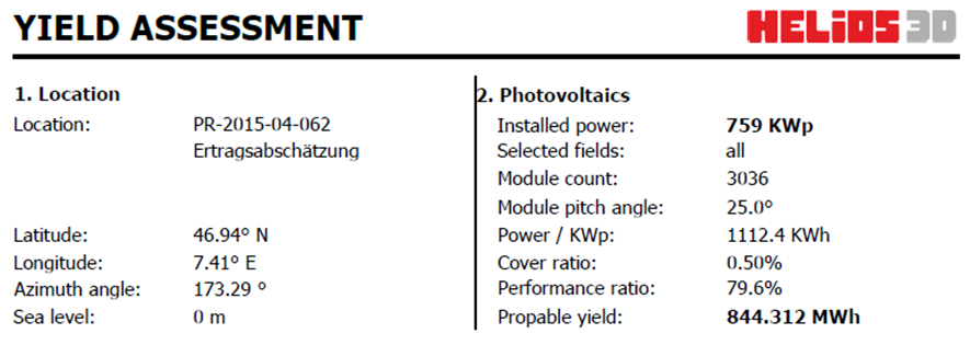
Results of the Yield Assessment
The results of the yield assessment are presented in a report, which can be saved in various formats (e.g., PDF or XLS).
The report header includes the location data (1) and a plot of the PV layout (2).
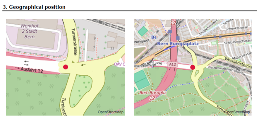
Below the geographic position is displayed in two maps (3). The radius shown in each map is determined by the settings in the “Calculation Parameters”. The values in the “Report Output” section (at the bottom) define the radii for the maps.
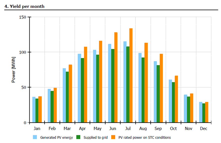
The power yield is displayed monthly in the following diagram (4).
The next section (5) shows the system power in a table. This table includes the global irradiance, average temperature, and the resulting calculations based on these factors.
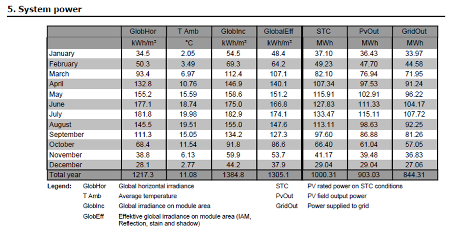
GlobHor: Global horizontal irradiance from the weather file. This represents the irradiance that hits a module when it is placed horizontally on the ground.
TAmb: Average temperature in 24-hour mode (includes night temperatures).
GlobInc: Global irradiance that hits the module area (considers the module’s inclination angle).
GlobalEff: Effective global irradiance, which is calculated as GlobalInc minus IAM (Incident Angle Modifier), minus reflection, minus stain, and minus shadow losses.
STC: PV rated power under Standard Test Conditions (STC).
PVOut: PV output power at the inverter.
GridOut: Power supplied to the grid.
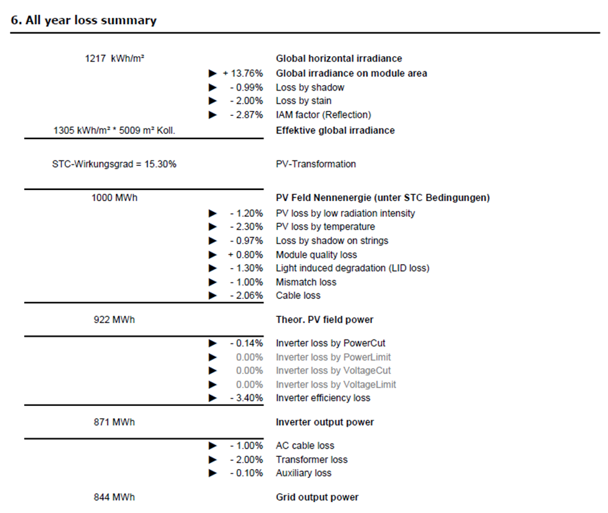
Section (5) does not include the electric layout or real shadows (e.g., from shadow objects). A calculation that takes these loss factors into consideration is displayed in the table of Section (6).
For all values to be calculated, the complete data for modules, combiner boxes, inverters, and transformers are required. If any values are missing, some of the subsequent calculations will be skipped. These skipped values are shown in gray, such as the inverter losses due to PowerLimit, VoltageLimit, and VoltageCut, as shown in the next figure.
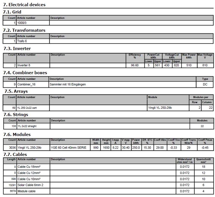
In the last section (7), there is a parts list that contains all the arrays and electrical devices from the layout.