Project and Drawing settings
In this section, comprehensive settings can be made for the project, the drawing, and the display. The project name, project number, and drawing number are fixed and cannot be changed afterward. However, you have the option to make adjustments to the location, date, and time zone information. Additionally, specific display settings can be defined within the project to optimally tailor the presentation to your requirements. These options allow you to precisely configure the project details and adjust the display according to your individual needs.
The Project and Drawing settings define basic project-related information, drawing assignment, geographic location, sun position parameters, and display behavior for the current drawing in Helios 3D. These settings are especially important before creating or updating PV layouts, shadow calculations, terrain-based planning results, and project-related evaluations.
Project number, project name, drawing number, and drawing description identify the database project and the registered drawing. If one of these fields shows Unknown, the drawing is not correctly linked to the Helios 3D project database and Helios 3D functions may not be available.
Geographic location, date, time, time zone, sun azimuth, and sun altitude are used for sun position and shadow-related calculations. These values should be checked before using placement, shadow, yield assessment, or analysis functions.
Note:
The geographic location used for sun position calculations is independent from the DWG coordinate system and from Civil 3D georeferencing settings. Changing the sun calculation location does not automatically georeference the drawing.
Section Project and Drawing Settings
This section contains the core project and drawing information for the current drawing. It also provides the location and sun position parameters that influence layout and shadow-related workflows. Before starting array placement or checking shading, verify that the drawing is correctly registered in the database and that the geographic location, date, time, and time zone match the intended planning scenario.
Important:
Some project and drawing identifiers are read-only because they are assigned during project and drawing creation. If they are incorrect, do not try to correct them in this dialog. Check the project and drawing registration in the database workflow instead.
Project Number
Project number this drawing relates to. If this box shows an ‚Unknown‘, the drawing is not correctly registered in the database, so no Helios functions will be available.
Project Name
Project name this drawing relates to. If this box shows an ‚Unknown‘, the drawing is not correctly registered in the database, so no Helios functions will be available.
Drawing Number
Drawing number of this drawing. If this box shows an ‚Unknown‘, the drawing is not correctly registered in the database, so no Helios functions will be available.
Drawing Description
Description of this drawing. If this box shows an ‚Unknown‘, the drawing is not correctly registered in the database, so no Helios functions will be available.
These fields are used to verify that the currently opened DWG belongs to a registered Helios 3D project and drawing record. They help identify which project database entry, drawing number, and drawing description are connected to the current drawing.
If Unknown is displayed, the drawing should be checked before continuing. Typical causes can include an unregistered drawing, a copied DWG that is not linked to the database, a missing project database connection, or an opened drawing outside the intended Helios 3D project workflow.
Recommended check:
If project or drawing information is displayed as Unknown, close the affected workflow step and verify the project and drawing assignment before using placement, electric planning, analysis, output, or evaluation functions.
Set Latitude
Insert latitude for the project location. This value is used for calculating the sun’s position and by that the shadings.
The geographic location is completely independent from sun and coordinate system settings inside Civil 3D.
Set Longitude
Insert longitude for the project location. This value is used for calculating the sun’s position and by that the shadings.
The geographic location is completely independent from sun and coordinate system settings inside Civil 3D.
Latitude and longitude define the geographic position used by Helios 3D to calculate the sun position. These values affect the calculated sun azimuth and sun altitude and therefore influence shadow-related planning results.
Use coordinates that represent the actual project site or the intended reference location for the calculation. If the project contains several planning areas, verify which location should be used as the representative calculation point.
Important:
Latitude and longitude are not the same as the CAD drawing coordinate system. They do not replace a correctly prepared DWG coordinate setup, terrain model, or survey basis.
Change Geographic Location
Allows changing the geo position in a dialog, which supports GPS or UTM data. Alternatively, the location can be read from KML/KMZ files or the AutoCAD geo location settings.
This geo position is exclusively used for the calculation of the sun angles and it’s independent from geo referencing for the DWG file, which can just be managed by the user.
Use Change Geographic Location when the project location should be selected or corrected with support from address search, GPS coordinates, UTM coordinates, KML/KMZ files, or AutoCAD geolocation information. The selected position is used for sun angle calculation and related shadow behavior in Helios 3D.
Before accepting the new location, check whether the displayed position matches the intended project site. A wrong geographic position can lead to incorrect sun azimuth, sun altitude, and shadow results.
Important:
Changing the geographic location for sun calculation does not automatically validate the quality, accuracy, or coordinate reference of survey data, terrain surfaces, imported objects, or the DWG itself.
Geo position and surface
The dialog for changing the geo position for the calculation of the sun position and resulting shadow on the project settings page has changed.
A new search location field has been added that uses a web service to search for an address. When an address is selected, the GPS coordinates get read and a map gets displayed in the background of the drawing.
The map uses the UTM84 coordinate system.
In the DTM / Surface section it is possible to optionally retrieve a free surface in UTM84 coordinates. This can be a compromise solution in case no better survey data are available, and at the same time it’s an alternative to the use of third party solutions such as Google Earth or Bing data.
The Geo position and surface workflow can help to initialize a project location and, if required, retrieve a basic surface when no accurate survey data are available. This can be useful for early feasibility checks, preliminary layout studies, or demonstration projects.
For detailed engineering, construction documentation, grading, or final PV layout decisions, externally verified survey data should be preferred whenever available.
Warning:
A surface retrieved from a web service may not have the same accuracy, resolution, update status, or legal reliability as project-specific survey data. Use it as a fallback or preliminary data source only unless its suitability has been verified for the project.
In the upcoming dialogue you can change both values.
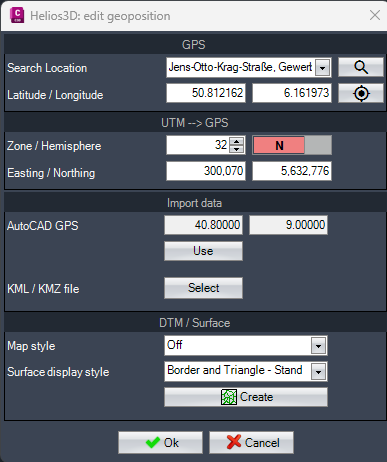
Search Location
Type in an address to receive a list of possible locations from the web. When a listed location gets selected, the background map of AutoCAD gets displayed with zoom to the location.
After selecting a search result, visually check the displayed map background and zoomed location. Similar place names, incomplete addresses, or different administrative regions can lead to selecting the wrong project location.
Recommended check:
Compare the selected location with known project information such as address, parcel location, survey reference, KML/KMZ source, or customer-provided site data.

Zoom to location
Zooms to the selected location in case the user has moved around inside the drawing.
Retrieve a surface from the web
Users who don’t have access to accurate survey data or who like to avoid the costs can now retrieve free data from https://www.gpxz.io/. The resulting surface uses UTM84 coordinates and chooses the proper zone automatically.
The retrieved surface is intended to provide a usable terrain basis when no better surface data are available. After insertion, inspect the surface extent, elevation behavior, and position before using it for array placement, terrain analysis, grading, or yield-related workflows.
Warning:
Do not assume that a web-retrieved surface is accurate enough for final engineering or construction planning. For binding planning results, check whether project-specific survey data are required.
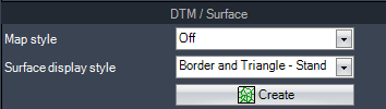
Map style
Sets the map style for the AutoCAD Map service for the drawing.
Surface display style
Sets the style the generated surface will be displayed with after insertion.

Starts the creation mode for importing a rectangular surface by showing the below prompt in the command line.
Map style affects the visual appearance of the AutoCAD map background. Surface display style controls how the generated surface is shown after insertion. These settings help users visually inspect the selected location and the retrieved terrain surface.
They do not by themselves change the calculated sun position, the project database assignment, or the engineering accuracy of the terrain data.
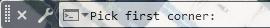
The user can pick the first corner of the area which immediately leads to the prompt below.

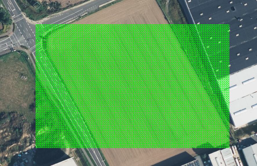
The result will be a rectangular TIN surface at a maximum size of 10 km². The surface immediately is ready to be used for creating a layout.
After the rectangular TIN surface has been created, check whether the selected rectangle covers the complete planning area and any relevant surrounding terrain that may influence the layout. If the selected area is too small, placement, grading, or terrain-based analysis may be incomplete.
Important:
The maximum size limit means that large project sites may require a careful selection of the surface area or a different terrain data workflow. This should be considered before starting detailed layout planning.
Absolute Altitude
Enter the height value for the absolute altitude. This value is used in the yield assessment and significantly affects temperature influences.
Absolute altitude represents the elevation value used in yield assessment and temperature-related calculations. Use a value that is representative for the project site. If the site has significant elevation differences, verify which reference altitude should be used for the assessment.
Recommended check:
Compare the entered altitude with survey data, the retrieved terrain surface, project documentation, or other reliable elevation sources.
Time zone
Set the time zone for the sun’s azimuth and altitude based on the specified date and time. Incorrect time zone settings will render all shadow calculations inaccurate. Always use the local standard time.
The time zone must match the local standard time of the project location. Incorrect time zone settings can shift the calculated sun position and produce misleading shadow results.
Important:
Use local standard time for the calculation reference. Daylight saving time or an incorrect regional time zone can lead to inaccurate sun azimuth and sun altitude values.
Enter Date / Time
Enter the reference date and time for the shadow calculation. All relevant fields will be initialized with this value to ensure shadow-free placement.
Sun azimuth and altitude calculations based on date and time follow the algorithm defined by DIN 5034.
The button „date/time“ sets the date and time to the default sun settings. The standard reference date for the northern hemisphere is December 21st at 12:00 PM, and for the southern hemisphere, it’s June 21st at 12:00 PM.
These reference dates are not intended as recommendations for the chosen geographic position.
The selected date and time define the reference situation for the shadow calculation. This value should reflect the planning rule, design scenario, or internal company standard used for checking shadow-free placement.
The default reference dates are technical defaults and are not automatically suitable for every project location, planning requirement, or contractual shading criterion.
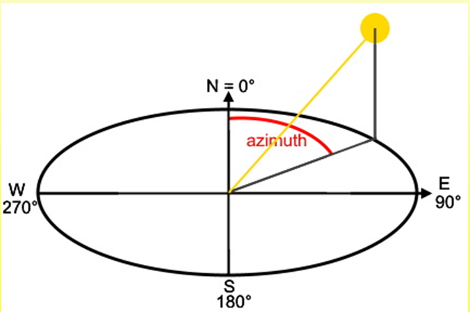
Azimuth (°) of the Sun
Azimut in degrees resulting from the current input in <Date / Time>, <Latitude> and <Longitude>. The sun position is calculated after DIN 5034 and has a range from 0 to 360 degrees, measured from north and clockwise.
Sun azimuth and sun altitude are calculated from date, time, latitude, longitude, and time zone. These values describe the direction and height of the sun for the selected reference situation and are used by Helios 3D for shadow-related workflows.
If the calculated values are unexpected, check the geographic coordinates, time zone, date, and time before changing the values manually.
Overwrite sun azimuth
Enable to overwrite the sun azimuth calculated after DIN 5034.
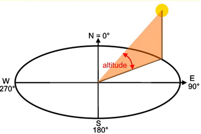
Altitude (°) of the Sun
Altitude in degrees, which is calculated for the drawing from the <Date / Time>, <Latitude> and <Longitude> settings.
Overwrite sun altitude
Enable to overwrite the sun altitude calculated after DIN 5034.
Use overwrite options only when a defined manual sun position is required. Manual values can be useful for testing, comparison scenarios, or special planning requirements, but they bypass the automatically calculated values based on DIN 5034.
Warning:
Manually overwritten sun azimuth or sun altitude values can lead to shadow results that no longer match the project location, date, time, and time zone. Document the reason for using manual values if the drawing is used for review, reporting, or handover.
Section Display Settings
Display Settings control how future placement results and array blocks are represented in the drawing. These settings are mainly relevant for readability, drawing performance, and the amount of label information shown during placement workflows.
Changing display settings does not necessarily change already completed planning decisions. Except for the complexity of array blocks, the options are applied to future table placement executions.
All options, except for the complexity of array blocks, are applied to future table placement executions.
Complexity of Array blocks
Select the level of detail for the blocks in any table insertion and update all blocks accordingly. Reducing the block details improves performance without affecting functionality.
Lower block complexity can improve drawing performance, especially in large PV projects with many arrays or module tables. Higher detail may be useful for checking geometry, presentation drawings, or detailed visual review.
Recommended check:
If drawing performance is slow, reduce the complexity of array blocks and update the blocks accordingly. This should improve handling without changing the functional planning data.
Check boxes and radio buttons
These checkboxes and radio buttons determine which labels are added during the placement process.
The available check boxes and radio buttons define which labels are created during placement. These labels can support orientation, checking, documentation, and review of PV layout results.
Choose label settings according to the current task. For example, a detailed checking drawing may require more labels than a performance-optimized working drawing.