
New Array Definition
When creating a new array definition, you will be prompted to select a component folder, as shown. Afterward, you will need to enter a name (or component number) for the array definition. All necessary insertions can be performed directly in the Array Generator. Once all required values have been provided, the geometry will be automatically calculated and displayed.
The New Array Definition is the starting point for creating a reusable rack or table configuration in Helios 3D. The definition combines the selected component folder, the array name or component number, module-related dimensions, structural settings, post configuration, and optional electrical information into one database-based array object. This array definition can then be used later during array placement and project-specific PV layout planning.
Input fields that still require a valid value are highlighted with a red frame, indicating that user input is needed.
A red frame indicates that the current input is missing, incomplete, or not valid for the next calculation step. Continue filling in the fields from top to bottom and check dependent values before editing later sections. Some fields can only be calculated correctly after module dimensions, module distances, or other required base values have been entered.
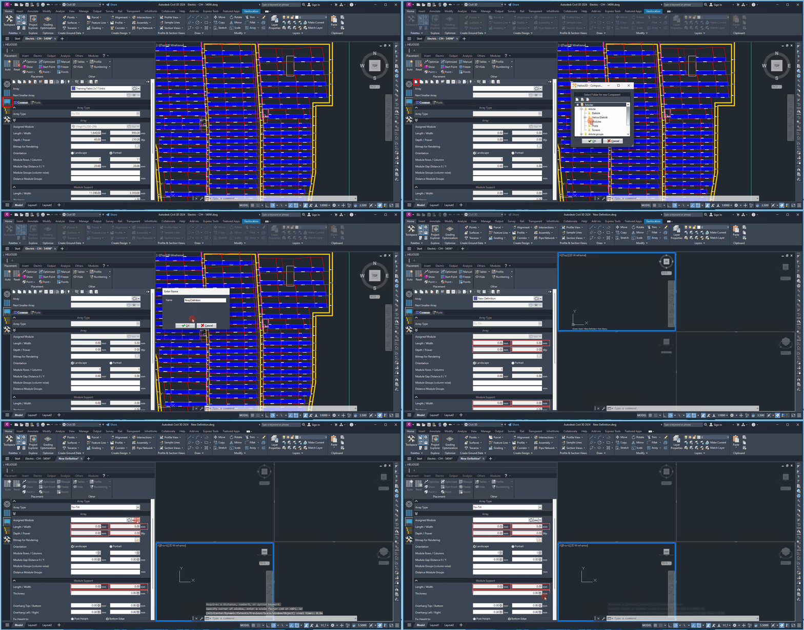
In the Array Generator, fields should be filled out in a top-down direction because some values are required for calculating subsequent values. For example, the “Length” and “Width” in the “Array Panel” section are determined by the module dimensions and the distances between the modules.
Because several values depend on previous entries, the recommended workflow is to complete the general array data first, then define the module and rack geometry, and only afterwards continue with posts and electrical settings. This helps avoid inconsistent dimensions and reduces the risk that calculated values need to be updated manually.
Module inclination can be adjusted for any placement within the field properties, allowing the same table to be used across different projects or locations.
The array definition should describe the reusable technical configuration of the rack. Project-specific placement properties, such as the final inclination used in a particular field, can be adjusted later where applicable. This makes it possible to reuse the same array definition in different projects or layout areas without creating unnecessary duplicate definitions.
Below, we will describe all sections of the rack generator, as shown in Figure. For clarity, each section is presented separately.
The first section includes the component number and naming for the rack, along with the option to connect smaller versions of the rack to the current rack definition.
Array
In this section, you can select an array definition from the list (database) or create a new one. If you need to modify a selected definition, you can do so using the „Edit Array Definition“ button located in the toolbar.
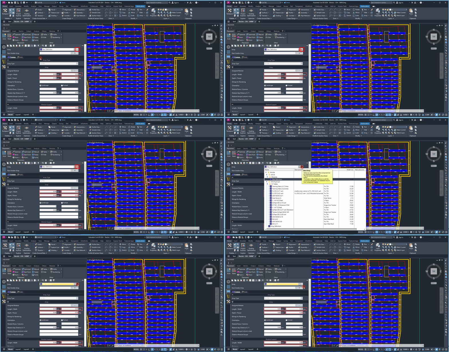
Use the selected array definition as the central configuration record for the rack geometry. If an existing definition is selected from the database, review whether it should be reused unchanged or edited with the “Edit Array Definition” button. Changes to a shared definition may affect other workflows or projects that use the same database entry. This should be editorially and technically verified before being documented as a warning.
The additional settings are organized into the following tabs: „Common„, „Rack“, „Posts„, and „Electric„.
Notes and troubleshooting
If the geometry is not calculated or not displayed as expected, first check all red-framed input fields and complete the values in the recommended top-down order. Also verify that the selected component folder and the array name or component number are correct. If length, width, or module-related dimensions appear incorrect, review the module dimensions and module spacing values before changing dependent rack settings.