
Array Generator
The array generator is used to create the geometry of an array necessary for planning, specifically for shadow-free placement in a terrain. This parametric array definition includes a rack and the modules assigned to it, along with additional values for calculating the array’s power.
The Array Generator is the starting point for defining the physical PV array object that will later be used during automatic or manual placement. The definition combines geometric, mechanical and PV-relevant information, such as the module arrangement, rack structure, support elements and calculation values for installed power. In Helios 3D, this array definition is reused throughout the placement workflow and should therefore be created carefully before starting the layout process.
To meet general placement requirements, such as ensuring shadow-free conditions, managing slope, or addressing other installation criteria, users can enter various limiting values. Helios will validate these limits during placement. If any limit values are exceeded, the user will receive a notification, and problematic locations may be skipped during placement (for example, when the maximum slope is exceeded).
The entered limit values are not only descriptive parameters. They influence whether an array can be placed at a specific position in the terrain. If the terrain, slope or placement conditions do not meet the defined limits, Helios 3D may reject the position, skip the affected location or notify the user. This helps to avoid technically unsuitable array placements during early layout planning.
The following example shows how an array definition is organized in the Array Generator. Depending on the selected array type and configuration, additional tabs or parameters may be available. The visible options can depend on the selected component type, project settings and available component data.
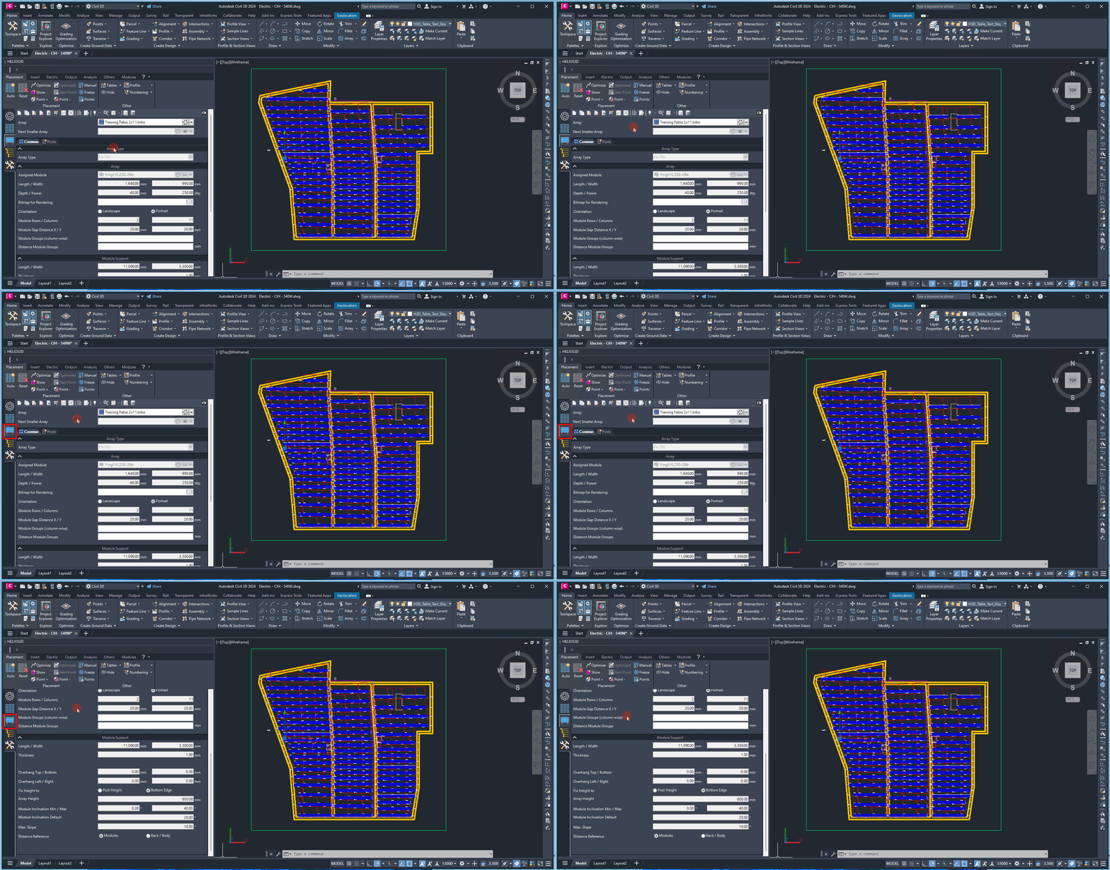
Before creating or editing an array definition, make sure that the required module, rack and support data are available. Missing or incomplete component data can lead to incomplete array definitions or placement results that do not reflect the intended PV layout. If values are unclear, they should be checked against the technical datasheets or internal project standards.
Each time you create a new definition for an array, module, rack, or post, you will be prompted to select a folder for the new component. This allows you to categorize all components as you see fit. The figure below provides an example structure for categorizing your components, although it is not mandatory.

This procedure enables you to store your component data in a manageable folder structure, which can be modified in Helios 3D Component Management. Additionally, it allows you to save.
A clear folder structure is recommended for long-term project work, especially when several array definitions, rack variants, module types or post configurations are used. Meaningful component folders make it easier to find, reuse and maintain definitions across projects. The folder assignment can be adjusted later in Helios 3D Component Management.
Typical follow-up steps after creating an array definition are checking the related array type, reviewing the Common tab, defining module support and post parameters, and verifying the resulting array drawing. These related chapters should be used to complete the definition before the array is used for placement in the terrain.
Important:
Incorrect limit values, incomplete component data or unsuitable geometry settings can directly affect placement results. If arrays are missing, skipped or placed differently than expected, review the array definition before changing the project area or terrain data.