
Module Support
The Module Support tab defines the geometric and technical properties of the rack structure used by an array definition in Helios 3D. These settings influence the calculated table dimensions, the rack height, the module inclination range, the required spacing between rows and arrays, and the checks against terrain slope limits.
Use this tab to describe how the modules are physically supported by the rack, including support thickness, overhangs, height reference, tracker rotation distance, and permissible inclination values. The resulting geometry is used as a reference for array placement, shadow-related distance checks, post settings, and layout validation.
The values in this area describe the physical envelope of the module support structure. They are not only descriptive values but may also affect how much space an array requires in the layout. For this reason, the values should match the intended rack system as closely as possible.
Length/Width
These measurement data are calculated based on the arrangement of the modules, their gap distances, and the overhang values specified below.
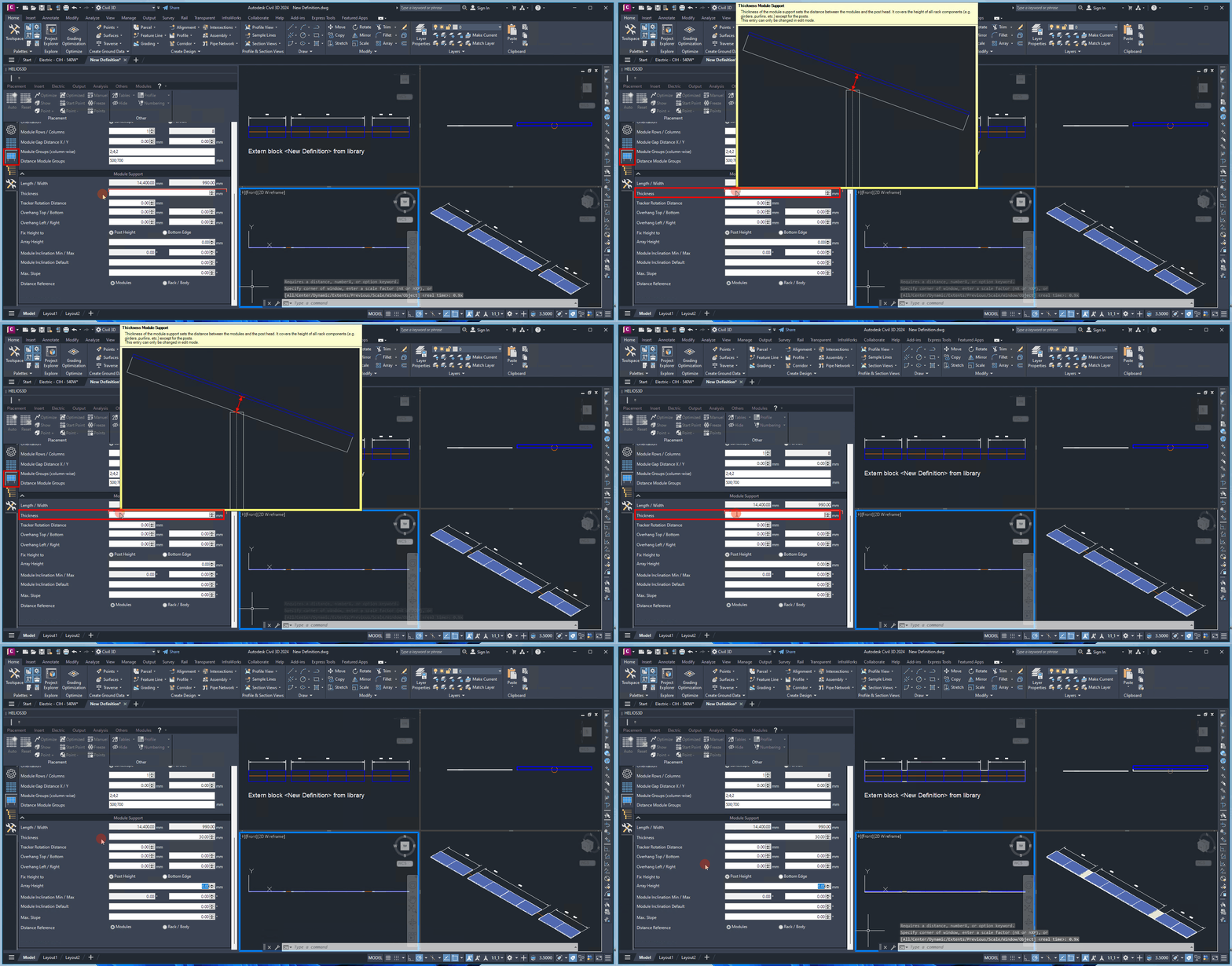
Thickness
Thickness of the Module Support. This value represents the height of all rack components (e.g., girders, purlins, etc.), excluding the posts. This field can only be modified in edit mode.
The thickness value should represent the vertical height of the rack components below the module plane, excluding the posts. It is relevant when the rack body must be considered for clearance, spacing, or tracker rotation geometry.
If the support thickness is too small or too large, the generated rack geometry may not represent the real mounting structure correctly. This can affect visual checks, distance references, and the maximum tracker rotation distance.
Just for single-axis- and multi-row trackers
For single-axis trackers, certain presets are applied to the array definition, and the „Rotation Distance“ option becomes active. For example, the array height is determined by the post height, and there is only one row of posts.
For trackers, the table body (highlighted in red) is always generated with no module tilt (0° inclination). The row distances are measured from table body to table body.
Tracker-specific settings should only be used when the selected array type represents a tracker system. For fixed-tilt racks, these settings may not be relevant or may remain inactive.
For single-axis trackers, the generated table body is handled differently from a fixed-tilt rack. The article states that the table body is generated without module tilt and that the row distance is measured from table body to table body. This makes the tracker-specific geometry important for layout spacing and shadow-related checks.
Tracker Rotation Distance
The Rotation Distance defines the position of the rotation point, measured as the distance from the post head for cases where the module has a non-zero inclination angle.
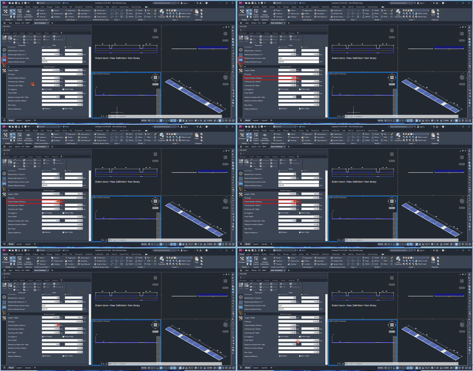
A value of 0.00 mm means that the modules rotate directly around the post head.
The maximum rotation distance is determined by adding the module support thickness to the module depth.
Use the rotation distance to define where the tracker axis is located relative to the post head. This is especially important when the module plane has a non-zero inclination angle in the array definition.
A rotation distance of 0.00 mm places the rotation point directly at the post head. Higher values move the rotation point away from the post head, up to the maximum value defined by the support thickness plus the module depth.
Typical check:
If the tracker geometry does not look correct in the table definition drawing, check the support thickness, module depth, inclination angle, and rotation distance together.
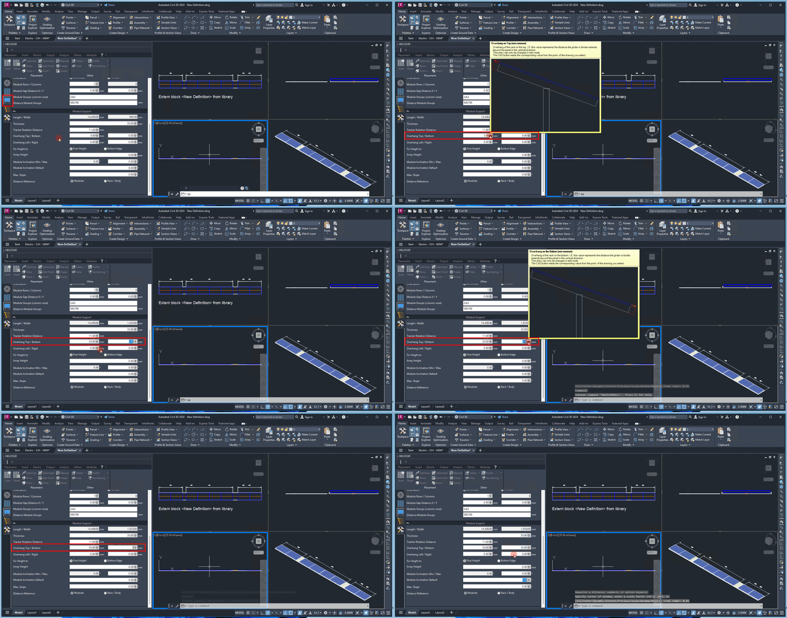
Overhang Top/Bottom
Here, you can enter the distance that the girders or binders extend beyond the module in the vertical direction (though this is not typical).
This measurement increases the total area required for an array, in addition to the area defined by the modules. These components must be taken into account when calculating shadows and the distances between rows and arrays within a row.
Overhang Left/Right
Here, you can enter the distance that the purlins extend beyond the module in the horizontal direction.
This measurement increases the total area required for an array, in addition to the area defined by the modules. These components must be considered when calculating shadows and the distances between rows and arrays within a row.
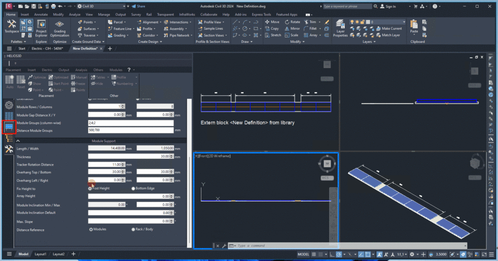
Overhang values increase the effective physical size of the array beyond the photovoltaic module area. They should be used when rack components extend beyond the module edges and must be considered for spacing, shadows, or physical clearance.
Top/Bottom overhang affects the vertical direction of the table body, while Left/Right overhang affects the horizontal direction. Both values can influence the total area required by the array and should therefore be checked before the array is used for placement.
Important note:
Overhang values should reflect the real rack geometry. Incorrect overhang values may lead to row distances, shadow distances, or array-to-array clearances that do not match the intended mounting system.
Fix Height To
The array height can be defined either by a fixed post height or by a fixed front edge height.
Post Height:
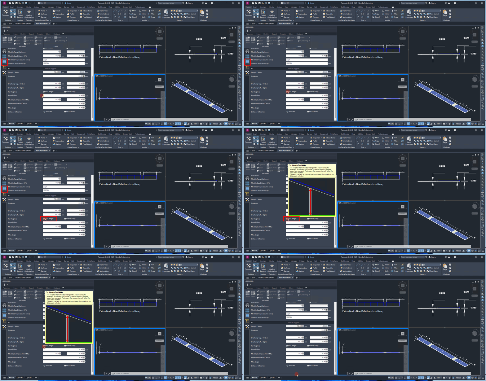
Front edge height: (measured from the photovoltaic active area)
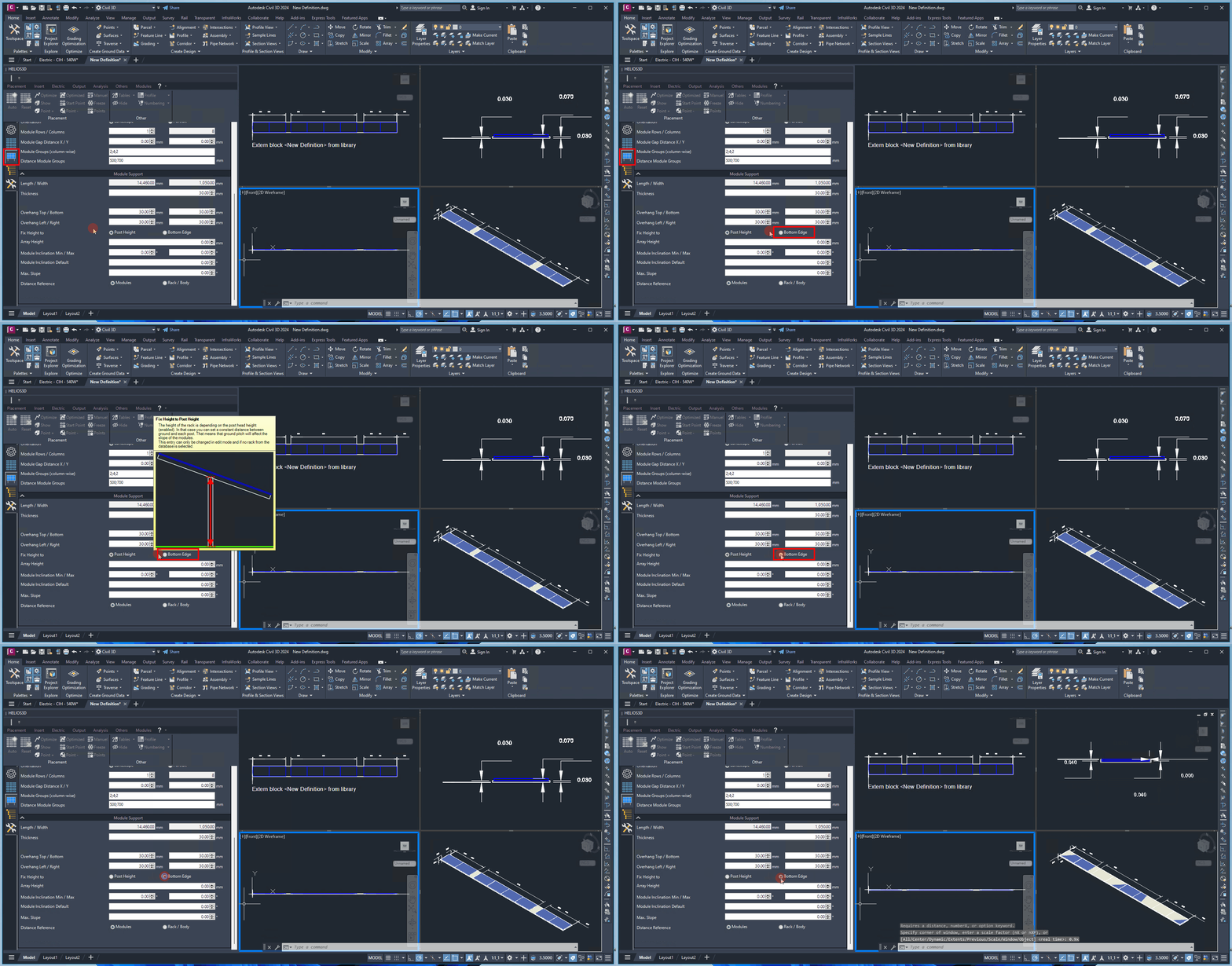
The height reference determines how Helios 3D interprets the array height value. If “Post Height” is selected, the height value refers to the post height. If “Front edge height” is selected, the height value refers to the front edge of the photovoltaic active area.
Choose the height reference according to the rack data available for the project. Structural rack specifications often provide post heights, while planning constraints or clearance requirements may refer to the lower module edge or front edge height.
Array Height
The „height“ value for the array specifies either the post height or the height of the front edge.
Module Inclination Min/Max (degree)
The angle range to which the modules can be adjusted on the rack serves as a reference in the project. This enables Helios 3D to detect any exceedance of technical limits.
Module Inclination Default (degree)
The default module inclination value is used to define the geometry displayed in the table definition drawing and serves as a reference for post settings.
The post distance settings are based on this inclination angle and will adjust accordingly for other angles.
The default module inclination is used as the reference angle for the table definition drawing and for post-related settings. The minimum and maximum inclination values define the permitted adjustment range of the rack.
If a project requires different inclination angles, the defined range helps Helios 3D identify whether the rack is used outside its technical limits.
Typical check:
If an inclination-related warning appears or a rack cannot be used as expected, compare the project inclination with the defined minimum, maximum, and default inclination values.
Max. Slope (degree)
For structural stability, racks can only be installed on slopes within a limited range. Here, you can specify the maximum allowable slope of the ground on which the rack will be placed.
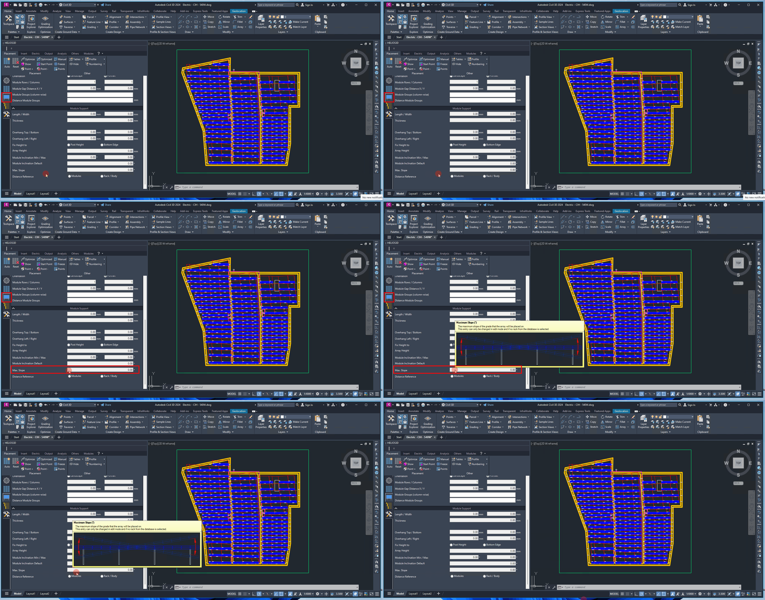
The maximum slope value defines the allowable terrain slope for placing this rack type. It is intended to prevent the use of a support system on terrain that exceeds the technical limits of the rack.
This value is relevant for layout validation on sloped terrain and should match the rack supplier’s installation limits.
Distance Reference (at Slope)
The sloped distance between two racks can be measured relative to either the array surface or the rack itself (with a <Floor> option coming soon). This distance considers the modules and may account for the overhang specified in the “General” tab, which will deactivate the “Overhang Left/Right” input fields.
When the reference is set to “Rack,” the distance is also verified at the bottom, which is necessary for configurations such as racks without posts.
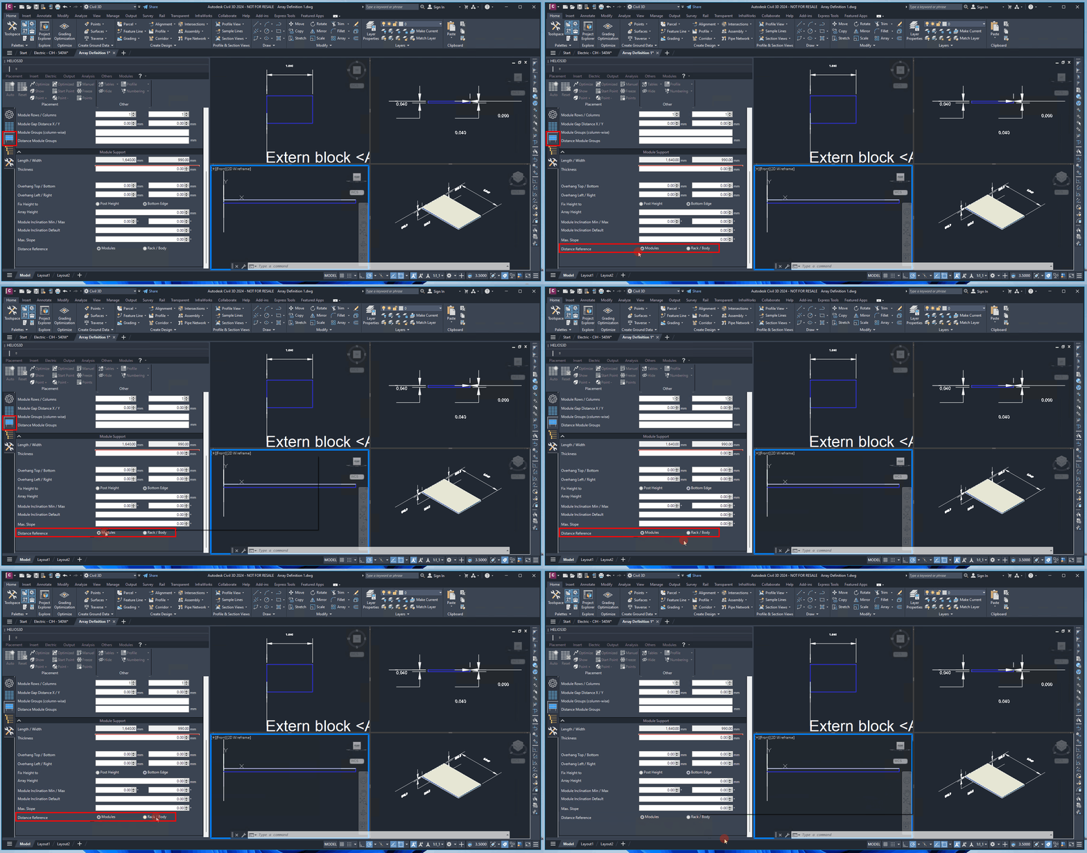
The distance reference determines how sloped distances between racks are evaluated. Depending on the selected reference, spacing can be checked relative to the array surface or relative to the rack body.
Use “Rack” when the physical rack body must be checked, for example when the lower part of the structure is relevant for clearance or when rack configurations without posts are used.