
Adjustment Lines
Adjustment lines are auxiliary CAD objects used to control how arrays are aligned or where rows start during array placement in Helios 3D. They help adapt the placement result to site-specific geometry, such as irregular field shapes, access corridors, exclusion zones, or required row directions. An adjustment line does not work globally by itself; it must be assigned manually to the corresponding field in the Placement structure.
You need to manually connect an adjustment line to a field. To do this, first select a field node in the structure tree under the „Placement“ tab.
Before using an adjustment line, make sure that the relevant field already exists and that the line object is located in a meaningful position relative to this field. The adjustment line should be created as a clean AutoCAD object and should match the intended placement logic. If the line is not connected to the field, it will not influence the placement calculation.
There are two types of adjustment lines: the row adjustment line and the start point adjustment line.
Row Adjustment Lines
Use a row adjustment line when the complete row direction should follow a defined linear reference instead of the default orientation. Use a start point adjustment line when the row start positions should be controlled while the placement still follows the selected placement and spacing rules. The correct line type depends on whether the main goal is row orientation or row starting position.
These elements are based on the AutoCAD „Line“ type and influence the alignment of the arrays. Instead of the default y-direction orientation (where the photovoltaic active area faces south/north), all arrays will be positioned parallel to the adjustment line.
This is useful when the PV layout must follow a site boundary, road, fence line, terrain corridor, or another planning reference. The row adjustment line changes the orientation logic of the placement but should not be understood as a replacement for field borders, exclusion zones, or placement settings. The final result still depends on the field geometry and the active placement parameters.
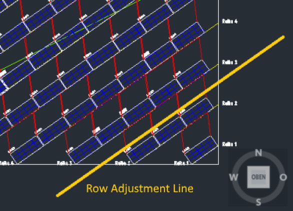
The figure below illustrates a placement with the adjustment line highlighted. The array orientation results in a south-east direction.
Start Point Adjustment Lines
This object utilizes the AutoCAD „Polyline“ type and determines the placement order of the arrays. In this case, the starting point for each row is located on the adjustment line. All arrays are positioned starting from the adjustment line and extend in both directions, to the left and to the right.
A start point adjustment line is especially useful when the first array positions of multiple rows should follow a defined geometric reference. This can help create a more regular visual layout or align rows with internal site structures. The exact result depends on the selected alignment option, the array distance, the placement direction, and possible restrictions such as exclusion zones or invalid insertion positions.
There are three options that can influence the precise use of this line.
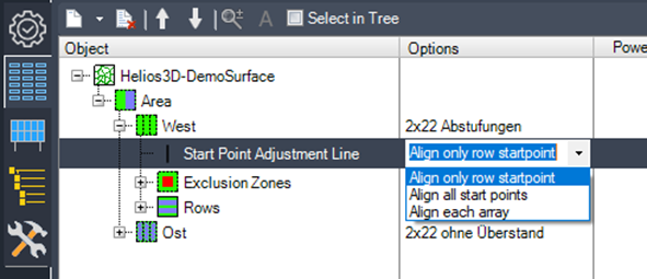
- Align only row start point:
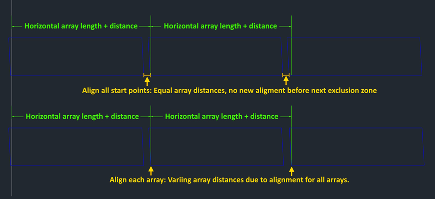
This option uses the polyline solely as the starting point for each row, without any further alignment. The behavior is similar to the placement from a field border without alignment. - Align all start points:
In this case, arrays are aligned according to each row segment (e.g., after an exclusion zone). Neighboring arrays maintain the set array distance. This option ensures more uniform array distances, based on the „Array Distance“ placement setting. - Align each array:
Each individual array within a row is aligned to its position on the even surface. This provides the highest level of alignment, resulting in significantly varying array distances.
The three options provide different levels of alignment control. “Align only row start point” has the least influence on the row geometry. “Align all start points” creates a more consistent alignment between row segments. “Align each array” provides the strongest alignment to the adjustment line but may lead to noticeably different distances between neighboring arrays. The option should therefore be selected according to the planning priority: visual alignment, regular spacing, or precise geometric control.
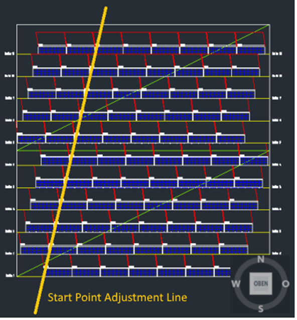
The figure below shows a placement with the start point adjustment line highlighted. The left and right lower corners of the arrays are positioned almost on the adjustment line. The small gap between them is due to the set distance between the arrays.
Placement Behavior with Start Point Adjustment Lines
The behavior of the placement with start point adjustment lines is influenced by the following placement options:
- Place Right Aligned: This option adjusts the alignment to ensure the arrays are placed right-aligned along the start point adjustment line.
- Array Distance: This setting places the arrays closer together while maintaining more uniform distances when alignment is based solely on the start points.
- Placement Increment: The user-defined increment can override the alignment rules, potentially causing a contradiction with the calculated positions.
When start point adjustment lines are used, small differences in placement settings can have a visible effect on the calculated insertion points. This is particularly relevant near exclusion zones, field borders, or when the adjustment line is outside the field. If the placement result does not match the expected alignment, check the assignment of the line to the field, the selected alignment option, the array distance, the placement direction, and the placement increment.
Below, we explain the effects of each option on the calculated insertion positions of the arrays.
Alignment and Array Distance
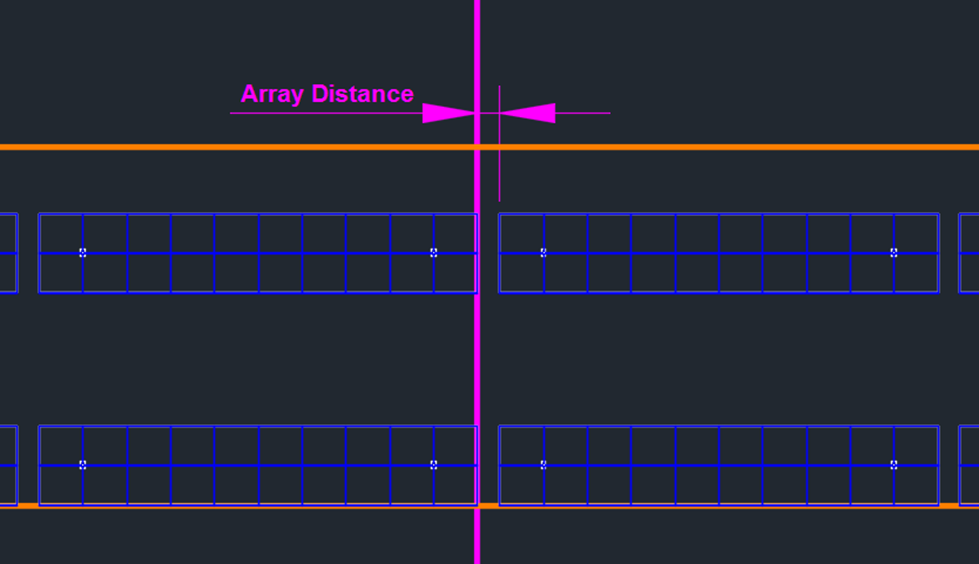
For a left-aligned placement, where rows typically run from left to right, the placement starts on the right side of the line. Once the row segment on the right side is complete, the arrays are then placed on the left side of the line, taking into account the set array distance. This ensures that the placement follows the specified array spacing while maintaining the alignment.

In contrast, the right-aligned placement starts on the left side of the adjustment line. In this case, the array distance must be respected on the right side of the line, ensuring that the spacing between arrays is consistent as the placement proceeds to the right.
Placement Increment with Start Point Adjustment Line
The placement increment defines the distance increment for Helios 3D when determining the insertion point of an array, especially when the original insertion point near the adjustment line is invalid.
If the adjustment line is outside the field or intersects an exclusion zone, the increment for the start point of the row parts can be calculated using either the full array length increment or a user-defined increment.
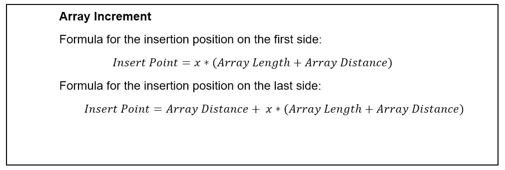
The array increment option ensures that arrays from multiple rows align in a serial manner. When a user-defined increment is applied, the step width for the offset from the adjustment line can be adjusted freely, for example, to match the increment with the post offset inside the array.
Placement alignment and array distance are also taken into account when calculating the increment.
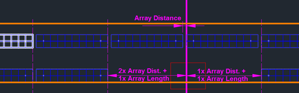
The figure below illustrates a left-aligned placement with the start point adjustment line in combination with an exclusion zone. In this example, the array increment is used, so on the left side of the adjustment line (placed last), the first array is placed after one array distance, plus an additional offset of x times the array length and array increment.
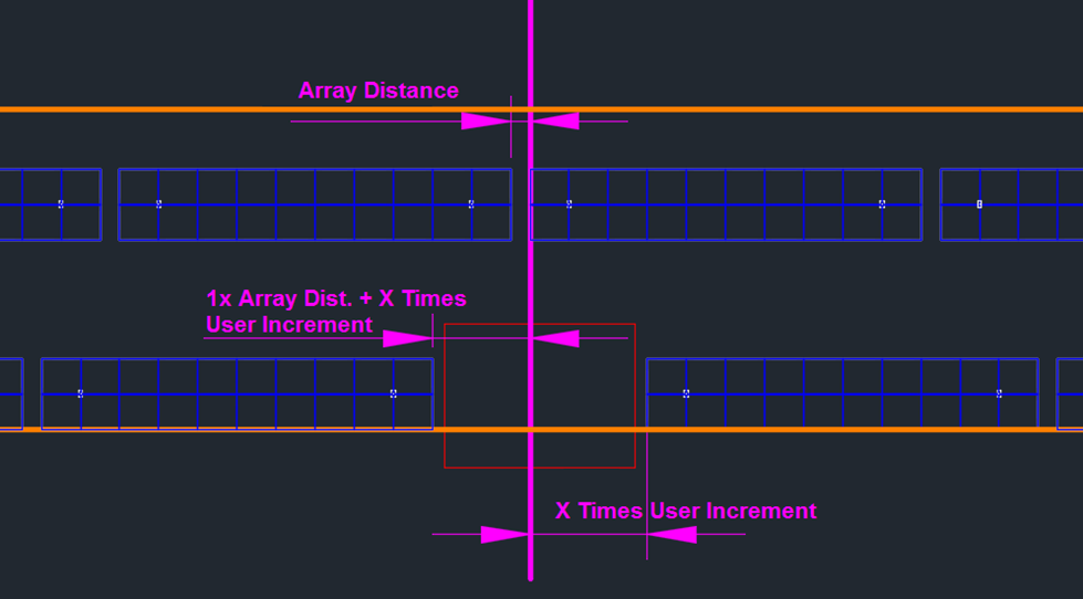
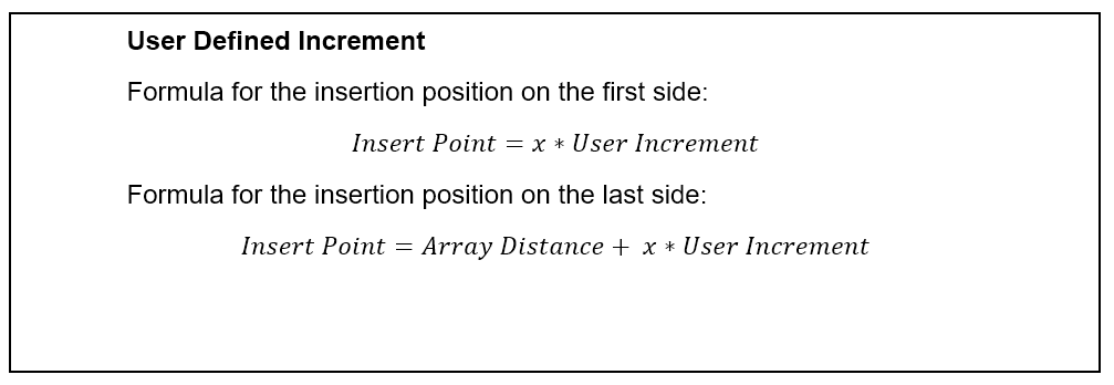
For the user-defined increment, the array distance is considered only once for the side of the adjustment line that is placed last. In the case of a left-aligned placement, this means the left side of the line will be where the array distance is applied.
Troubleshooting and Checks
If an adjustment line does not influence the placement result, first check whether the line has been assigned to the correct field in the Placement structure. Also verify that the CAD object type matches the intended function: a row adjustment line is based on an AutoCAD Line, while a start point adjustment line is based on an AutoCAD Polyline. If the result is shifted or does not align as expected, review the selected alignment option, the array distance, the placement direction, and the placement increment. Exclusion zones or field borders may force Helios 3D to calculate alternative insertion positions.