
Split Lines
Split lines consist of polylines and are automatically connected to one or more fields by Helios 3D. A split line can be used to divide a field into two separate sections.
Split lines are used during layout preparation when a large field needs to be divided into smaller planning sections. This can be helpful for organizing array placement, separating construction areas, or preparing different field parts for further processing in the PV layout workflow.
The split line itself is drawn as a polyline. After the splitting process, Helios 3D creates new field borders based on the position of the split line and the selected offset settings.
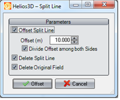
Before using a split line, make sure that a valid field exists in the drawing and that the polyline used as the split line crosses or touches the field in a way that can create separate field sections. If the polyline does not intersect the field correctly, the field may not be split as expected.
Offset Split Line
This option activates the offset parameters for the split line. If not enabled, the new field borders will be placed exactly on the split line.
Offset (m)
Here, you can specify the offset in meters, determining how far the new field borders are positioned from the original split line.
Use the offset value when the new field borders should not be placed directly on the original split line. This can be useful if a corridor, road, maintenance path, construction gap, or other separation distance is required between the resulting field sections.
Divide Offset among both Sides
This option evenly divides the offset value between both sides of the split line.
When this option is enabled, the entered offset is distributed equally to both sides of the split line. When it is disabled, the offset behavior should be checked in the drawing result. This behavior should be verified in the project drawing before continuing with array placement.
Delete Split Line
The split line will automatically be deleted once the splitting process is successful.
Delete Original Field
The original field will be automatically deleted if the splitting operation is successful.
Deleting the original field can help keep the drawing clean after the split operation. However, only enable this option if the newly created field sections have been checked and the original field is no longer needed. If you want to keep the original field as a reference, leave this option disabled.
For your workflow, we recommend drawing an area and using the „Offset“ function in AutoCAD to create a large field. Afterward, you can use split lines to divide the large field into smaller sections. This approach can be easier and faster than manually drawing multiple fields by entering points with your mouse.
After splitting a field, check the resulting field borders before continuing with array placement. Verify that the new sections are located on the correct layer, that the borders are closed, and that the intended planning area has not been changed unintentionally.
If the split result is not correct, undo the operation, adjust the split polyline or offset settings, and repeat the process.
Warning:
The options Delete Split Line and Delete Original Field remove objects from the drawing after a successful split operation. Use these options only when you are sure that the original objects are no longer required.