
Horizon Line
A horizon line marks the horizon projected within a fixed radius from a central location at a specific point in time. It can be used to calculate the shadows of objects (such as mountains or buildings) that are at a greater distance from the terrain.
A horizon line is mainly used when distant objects outside the immediate project terrain can influence the shading situation of the PV plant. Typical examples are mountains, hills, tree lines, buildings, or other elevated objects that are not modeled as local shadow objects in the drawing but still affect the solar horizon.
In Helios 3D, the horizon line supplements the local terrain and shadow object information. It helps the user include far-distance shading effects in the shadow calculation without having to model every distant object as a 3D object in the CAD drawing.
You can obtain the basic data for a horizon line from the company Solmetric and their measuring instrument, Suneye. The measuring data can be imported into Helios 3D (as well as PVsyst, etc.) from a text file with the file extension .HOR. Helios will automatically insert the horizon line into the active drawing.
A horizon line can also be created as an object in your Helios database, allowing it to be displayed in the structure list. Once created, you can view the measuring data in the properties of the selected horizon line within the structure list.
Properties
Before creating or importing a horizon line, make sure that the active drawing belongs to the correct project and that the measuring position is known. The center point of the horizon line should correspond to the location where the horizon data was measured, for example the position of the Suneye device.
The imported .HOR file should contain valid horizon measuring data. The exact file content and format should be checked if the horizon line is not inserted or if the resulting shadow calculation does not match the expected shading situation.
In the properties, you can define a horizon line (measuring data), and during this process, it will automatically be inserted into the active drawing. Afterward, you can calculate the shadows caused by the horizon line using the settings displayed in the following figure.
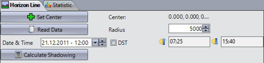

The center point defines the reference position for the horizon line in the drawing. It should be placed at the same location where the horizon measurement was taken. For reliable results, use a top view when selecting the center point and verify that the point lies in the correct project area.
Sets the center of the horizon line by manually pointing to the location in the drawing (top view recommended). This location corresponds to the position of the Suneye when the measurements were taken.
Radius (m)
The radius controls how far the generated horizon line is drawn from the selected center point. It does not describe the real distance to every measured object. Instead, it is used to project the measured horizon angles into the drawing at a fixed distance around the measurement location.
If the radius is too small or too large for the current drawing scale, the horizon line may be difficult to inspect visually. The shadow calculation is based on the measuring data and the defined settings, not on manually drawn mountain or building geometry.
The radius refers to the distance between the center (location of the Suneye) and the horizon line.

Reads the measuring data from a text file (file extension .HOR) and inserts the horizon line into the drawing, considering the radius and center point. This text file contains pairs of numbers, where each pair represents a location on the horizon line (expressed in degrees between -180 and 179) and an angle. These measuring data can be obtained from the Suneye measuring instrument by the company Solmetric.
After importing the .HOR file, check whether the horizon line has been inserted into the active drawing and whether the object appears in the structure list. If the imported data is not visible, verify the selected center point, the radius, the active drawing, and the validity of the .HOR file.
Plausible, but not confirmed by the page: If the file cannot be imported, the cause may be an invalid file structure, unsupported data content, a wrong file extension, or missing access rights to the file location. This should be verified by support or technical documentation before being added as a confirmed troubleshooting statement.
Date & Time
The selected date and time determine the sun position used for the shadow calculation. Use a date and time that represent the planning or analysis scenario you want to evaluate. Different dates and times can produce different shadow results because the sun path changes during the year and during the day.
The date and time for calculating the shadows caused by the horizon line.
DST
Use the DST option only if daylight saving time applies to the selected date and project location. An incorrect DST setting can shift the calculated sunrise and sunset times and may lead to unexpected shadow results.
Activate daylight saving time (checked) to add one hour to the times of sunrise and sunset.
Sunrise
The calculated time for sunrise on the set date.
Sunset
The calculated time for sunset on the set date.

Runs the shadow calculation.
After running the shadow calculation, review the drawing result and compare it with the expected shading situation. If the shadow result looks incorrect, check the measurement position, imported .HOR file, radius, date and time, DST setting, and project location data.
Plausible, but not confirmed by the page: The shadow result may also depend on other project settings, terrain data, local shadow objects, or the general shadow calculation settings used in Helios 3D. This should be reviewed before adding more detailed dependencies to the Help Center.