
Shadow Objects
Shadow objects have faces that can cast shadows on terrain and PV arrays. You can add (draw) shadow objects from the Helios 3D Library or register an existing object in the database as a shadow object.
Shadow objects are used when external objects such as trees, buildings, poles, bushes, walls, or other obstacles may influence the available irradiation or the usable layout area of a PV project. In Helios 3D, they are part of the placement workflow and can be used to evaluate how objects outside or inside the planned PV area affect terrain-based shadow projection and PV array placement.
Shadow objects do not replace a detailed yield simulation. They provide a CAD-based planning aid for visualizing and calculating shadow areas within the drawing. For project-specific yield assessment, the calculated shadow information should be interpreted together with the layout, array geometry, terrain data, and the project location settings.
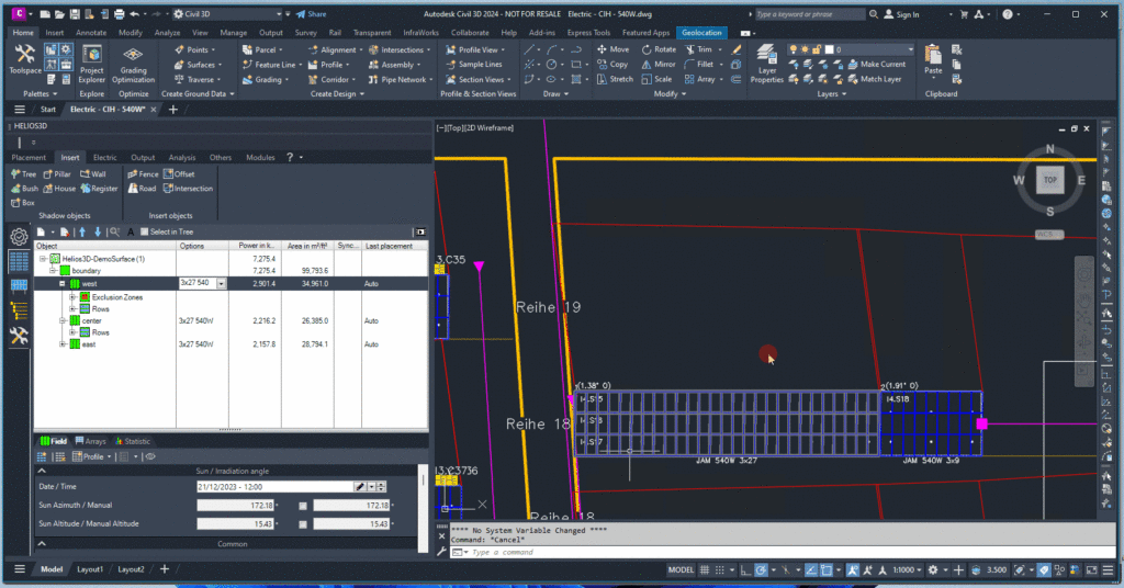
We recommend using the shadow objects provided via our “Draw” function. These objects are designed to represent most real-world objects in an abstract yet sufficiently accurate manner. The following menu screenshot displays a list of the available shadow objects:
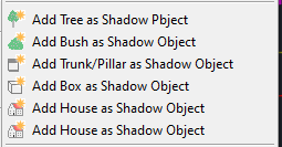
All objects shown in the figure are stored in the subdirectory \Library\ShadowObjects within your Helios 3D installation.
Draw / Insert Shadow Object
Use the predefined shadow objects whenever possible. These library objects are optimized for typical planning cases and are intentionally simplified. A simplified object with fewer faces usually provides sufficient shadow accuracy while keeping calculation times manageable.
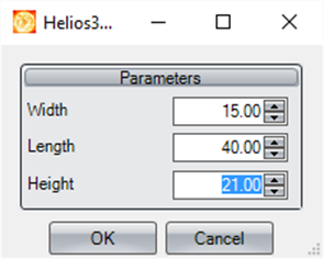
Typical examples include trees, bushes, trunks or pillars, blocks, and houses. The object type determines which scaling parameters are required. For example, elongated objects such as blocks or houses require a length value and can be rotated after insertion, while round or compact objects such as trees, trunks, pillars, and bushes do not require a length value.
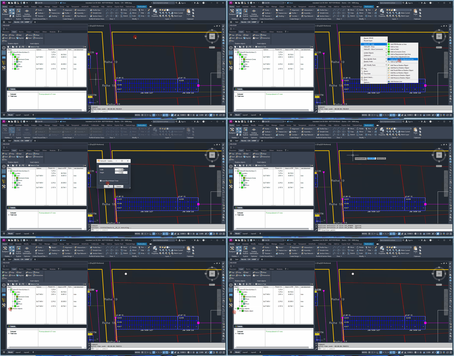
To insert a shadow object, please follow these steps:
- Enter Name: Provide a unique name for the object.
- Scale Object: Adjust the size of the object as needed.
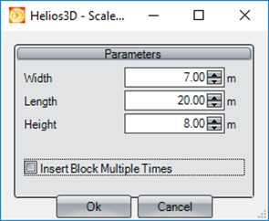
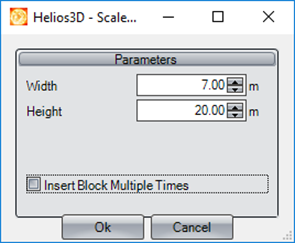
For blocks and houses, you need to specify a length. In contrast, trees, trunks/pillars, and bushes do not require a length to be set.
- Insert Object into the Drawing: Position the object by pointing at the desired location with your mouse. If the object is placed on a terrain, Helios will automatically adjust its height.
- Rotate Object: This step applies only to objects that require a length value for scaling. Adjust the orientation as needed.
Once inserted, the shadow object will appear in the “Structure” list within the “Placement” tab.
The entry in the Structure list is important because it confirms that the inserted object is managed as a shadow object in the placement context. From there, the object can be selected and its shadow calculation properties can be accessed. If the object is visible in the drawing but does not appear in the Structure list, check whether it was inserted or registered as a shadow object and not only added as a normal CAD object.
Register Shadow Object
Registering a shadow object is intended for cases where the predefined library objects are not sufficient for the planning task. This may be useful for project-specific obstacles, imported 3D objects, simplified building shapes, or custom terrain-related objects.
Only use custom objects when their geometry is necessary for the planning result. The more complex the object is, the more faces must be processed during shadow calculation. This can increase calculation time and may reduce drawing performance.
If the provided shadow objects do not meet your requirements, you have the option to register custom objects in the database. This can be done using the object itself or by defining it as a block.
The following points should be taken into account:
- Simplicity of Objects: The objects used should be as simple and abstract as possible. Adding unnecessary details increases the number of faces and the computational load, without improving the quality of the results.
- Supported Object Types: Only objects of the AutoCAD types “Mesh” (using the command
MESHor the interface shown in Figure 147) and “Polyface Mesh” (using the command3DMESH) are compatible.- For meshes, you can select a base object (e.g., mesh box, mesh pyramid, etc.) from a predefined list and customize it further.
- Polyface meshes are typically imported from external applications, such as Autodesk 3ds Max. Creating such objects directly in Civil 3D is complex and inefficient.
- Object Positioning: After placing the objects in the drawing, ensure they are fully elevated above the Digital Terrain Model (DTM). Objects that intersect the terrain may cause issues with shadow calculations due to the current development limitations.
Before registering a custom object, verify that the geometry is really a supported mesh object. Solids, surfaces, blocks containing unsupported object types, or visually similar CAD objects may not be suitable unless they are converted or built as supported mesh geometry.
To register an object, please follow these steps:
- Insert the Object: Insert the object into the drawing. You can either create and customize the object directly within the Helios drawing or open a separate drawing in Civil 3D to do so.
Please refer to the additional notes in section 7.10.2.1 for further details! - Raise the Object: Elevate the object to the desired height. When placing the object on the terrain, ensure it is fully raised above the terrain, ensuring there is no contact with the surface.
A registered object must be positioned completely above the DTM before the shadow calculation is started. If the object intersects the terrain surface, the resulting shadow may be incorrect or the calculation may fail. Use a side view, 3D view, or the height adjustment tools to verify that the object is not partially embedded in the terrain. - Add Area Definition: In the „Placement“ tab, click on Add Area Definition and then select Register Shadow Object….
- Assign a Unique Name: Enter a unique name for the object.
Afterwards, the shadow object will appear in the „Structure“ list under the „Placement“ tab.
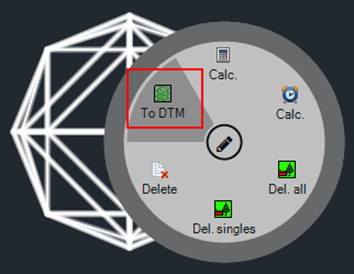
Since a registered object is not automatically raised above the surface, you can use the „Adjust Height“ command from either the radial menu or the context menu to position it correctly.
The height adjustment should be checked especially after importing external geometry or after moving an object manually. A visual placement in top view is not sufficient to confirm the correct elevation. The shadow object must be placed correctly in 3D space relative to the DTM.
Remarks on Creating / Customizing Shadow Objects
To create and customize shadow objects, you can start a Civil 3D drawing without using Helios. However, it is recommended to store any drawing related to shadow objects in the subfolder .\Library\ShadowObjects of your Helios installation. This way, anyone can easily use the object by inserting it into a Helios drawing as a block.
To create or customize an object, switch your workspace from „Civil 3D“ to „3D Modeling“. In this workspace, you will find the „Mesh Modeling“ tab in the ribbon bar, which contains all the command groups available for mesh creation and manipulation. This user interface provides an easier way to work with meshes, so you don’t have to remember the commands like MESH or those for customization.

When modeling a shadow object based on a primitive, it is important to minimize the number of faces used. The performance of any subsequent calculations or optimizations should be carefully considered, and for this reason, it is recommended to avoid using functions that increase smoothing.
Additionally, you should avoid modeling objects with holes, as holes are not necessary for casting shadows.
To set the number of faces for a primitive (such as a mesh box, mesh cone, etc.), you can adjust the settings in the dialog by clicking the small arrow (mark 1).
For customizing a primitive, use the commands in the „Mesh Edit“ group (mark 2). You can also edit subobjects, such as moving, rotating, or scaling vertices, edges, or faces (mark 3).
For a detailed overview of functions and modeling options for meshes, refer to the Civil 3D documentation. For quick learning, you can explore other resources, such as YouTube, using the search term “autocad mesh modeling.” Keep in mind that different versions of Civil 3D or AutoCAD may offer varying functionalities.
Modeling Example Telephone Pole
Here is a modeling example for creating a telephone pole using a mesh box:
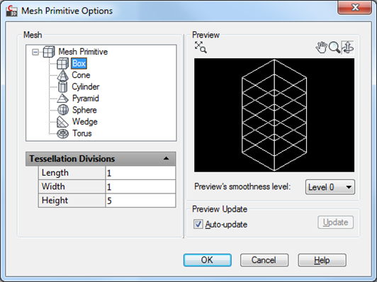
- Set the Number of Faces for the „Mesh Box“ Primitive:
Open the options dialog for the „Mesh Box“ by clicking the small arrow (marked 1 in the privious Figure). In the dialog, adjust the number of faces as shown in the example below. This allows you to control the complexity of the mesh and keep the number of faces to a minimum for better performance.
- Insert a Mesh Box and Move the Edges:
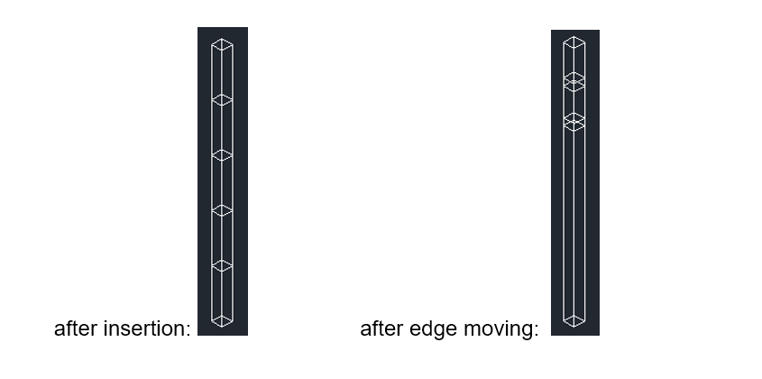
After setting the number of faces for the „Mesh Box“, insert it into your drawing. To shape the telephone pole, move the edges of the inner segments upwards.- First, set the filter for subobjects to „Edges“.
- Then, use the „Move Gizmo“ (buttons marked as 3) to move the edges as shown in the example below. This allows you to adjust the vertical position of the edges to form the desired shape of the pole.
- Extrude the Faces to Create Cross Girders:
Now, to create the two cross girders, we will extrude the faces on the left and right sides of the small segments.- First, select the two faces on the corresponding sides of the mesh (use the „Faces“ filter at mark 3).
- Next, click on „Extrude Face“ (marked 2) to extrude the selected faces one side at a time. This will extend the faces and create the cross girders as shown in the example below.
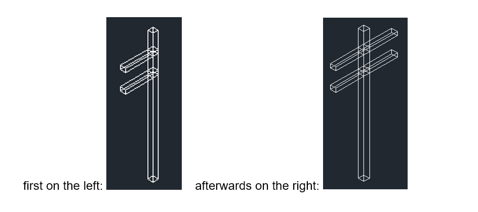
- Reduce the Number of Faces Using „Merge Face“:
To optimize the mesh and reduce the number of faces, use the „Merge Face“ command (marked 2). This command merges all coplanar faces on the front and back sides of the object, simplifying the geometry without losing the overall structure.
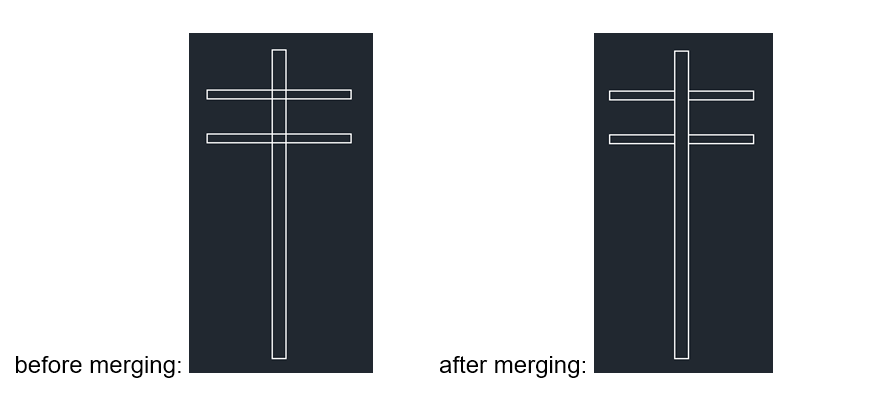
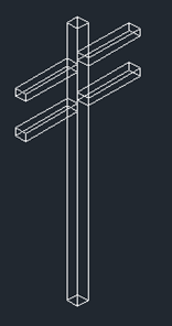
As a result, you will have a simple and abstract telephone pole model that can still cast a shadow with sufficient accuracy, even when compared to a more detailed model. This approach ensures optimal performance while maintaining the necessary level of detail for shadow calculation.
Properties (Shadow Calculation)
In the „Properties“ of one or more selected shadow objects, you will find all the functions related to shadow calculation, as shown below. These settings allow you to adjust parameters that affect how the shadows are generated and displayed in the drawing.
After a shadow object has been inserted or registered, the shadow calculation settings define when and how the shadow is calculated. These settings are project-dependent because the sun position depends on the selected date, time, daylight saving setting, and the geographical project location.
The calculated shadow is displayed in the drawing and can be used to visually assess whether planned PV arrays, rows, or available areas may be affected by surrounding objects.
Buttons
Each button adds the corresponding object to your drawing, allowing you to assign a name and adjust the scaling parameters based on the type of object.
Insert Tree

Inserts a tree into the drawing.
Insert Bush

Inserts a bush into the drawing.
Insert Trunk/Pillar

Inserts a trunk/pillar into the drawing.
Insert Block

Inserts a block into the drawing.
Insert House

Inserts a house into the drawing.
Move block to DTM height

Lifts a block above the surface.
Propose Shadow Offset

The „Propose Shadow Offset“ reads the minimum rack height set in the array definition within the array generator and writes the result into the input field. If the drawing contains array definitions with different minimum rack heights, an information box will appear, and the lowest value will be used by default.
Calculate

Starts the shadow calculation for the selected shadow objects and the chosen calculation day below. The calculation is based on the specified calculation options.
Reference Dates

Starts the shadow calculation for the selected shadow objects and for the dates 03/21, 09/21, 06/21, and 12/21. The calculation is based on the specified calculation options.
Calculation Options
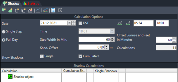
Calculation options should be selected according to the planning question. Use a single-step calculation if you need to inspect the shadow situation at one specific time. Use a full-day calculation if you need to understand the shadow movement throughout the day. Use the reference dates if you want to compare typical seasonal shadow situations.
You can set the calculation options for the shading of objects as well as for the display of the results.
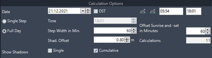
Date
Here you can enter a date for the shadow calculation.
Summer Time
Here you can activate summertime. When activated, one hour is added to the times for sunrise and sunset.
Sunrise

Here, the time for sunrise is displayed. This value is calculated based on the „Date“ and the project settings for the geographical position (see section „Fehler! Verweisquelle konnte nicht gefunden werden.“) with consideration of the summer time settings.
Sunset

Here, the time for sunset is displayed. This value is calculated based on the „Date“ and the project settings for the geographical position (see section „Fehler! Verweisquelle konnte nicht gefunden werden.“) with consideration of the summertime settings.
Single Step
This option is for calculating the shadow at a specific time between sunrise and sunset. Selecting this option activates the „Time“ input field and deactivates the input fields for step width and offset.
Time
Here you can enter a time between sunrise and sunset when the „Single Step“ option is selected.
Full Day
This option calculates the shadow movement throughout the entire day (from sunrise to sunset), based on the settings for step width and offset.
Step Width in Minutes
The step width defines the time intervals for shadow calculations. These values can be set between 15 and 60 minutes.
Offset Sunrise and Sunset in Minutes
This value specifies the offset to sunrise and sunset for the calculation interval. The calculation will start at sunrise plus the offset and end at sunset minus the offset. Values between 0 and 120 minutes are accepted. This function is useful for skipping calculations at times when the sun’s angle is very flat, which results in low efficiency for PV arrays and extremely long shadows.
Enter Shadow Offset (mm/in)
Here you can enter a shadow offset in millimeters or inches. Calculated shadows will be displayed above the original surface (DTM) at the distance specified by the offset value. This shadow is a projection onto an imaginary surface, which is the original surface raised by the offset value. When the offset equals the height of the front edge of the first module row, the shadow cast is shortened by the parts that are cast between the modules and the digital terrain, without shadowing the modules.
The shadow offset is especially relevant when the shadow should be evaluated at module height instead of directly on the terrain surface. A suitable offset can help represent whether a shadow would actually reach the active module area or only fall below the module level.
Calculations
Here you can see the total number of calculations for each of the selected shadow objects. This value updates whenever any of the values for sunrise, sunset, step width, or offset are changed.
Show Shadows
Here you can select which shadow layers should be thawed and which should be frozen after being inserted into the drawing. By default, only the cumulative shadow layers are thawed.
If shadows are not visible after calculation, check the layer visibility settings first. Shadow results may exist in the drawing while their layers are frozen or not displayed. Also verify that the selected date, time interval, sunrise and sunset settings, and shadow offset are appropriate for the project location.
For large projects or complex custom objects, reduce the number of faces in the shadow object and increase the step width where appropriate. This can reduce the number of calculations and improve performance.