Workflow for a surface grading
This document describes how to prepare a surface for grading and how to do a complete grading.
Most important on the preparation is that placement conflicts as module-DTM distances must not get handled during PV table placement, as you can either handle conflicts or do a grading based on invalid distances to the surface.
The used example shows a single-axis tracker design and the grading is done by the distances between the modules at their maximum rotation point (east and west) and the surface.
Considering post lengths for grading is not supported at the current state of development.
- The placement must be executed with a minimum module-DTM distance and trackers that cause a conflict must get inserted anyway, so we have a reference for cut and fill operations.
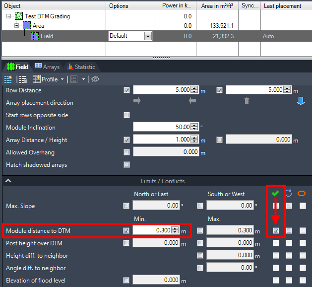
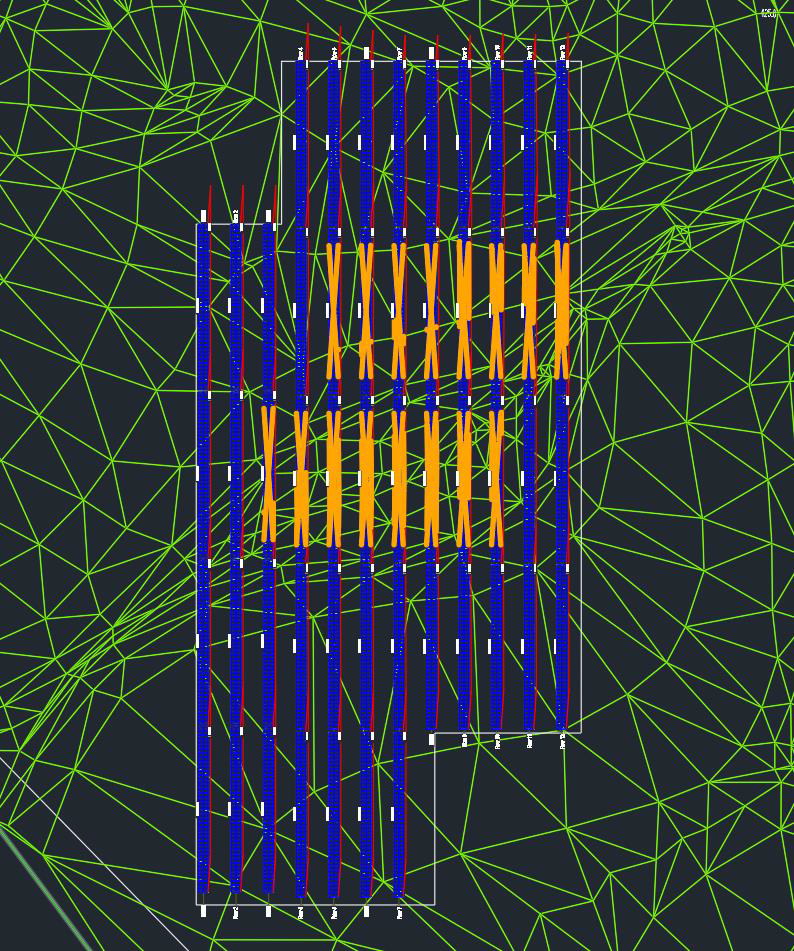
- The resulting layout shows collision markers to several trackers that have a shorter distance to the ground than 0.3 m, when modules are in their maximum rotation point to east or west.
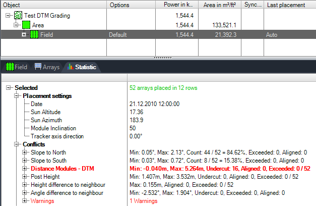
The placement statistic page even shows actual collisions and highlights them in red color.
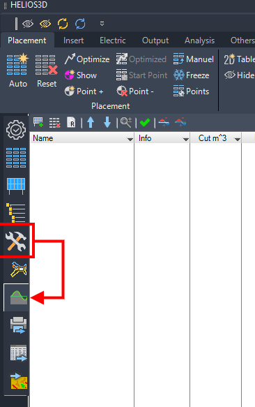
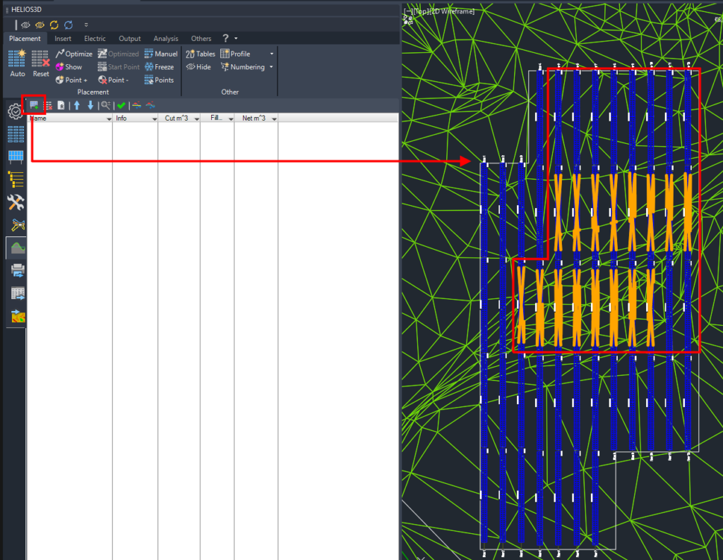
- For the grading, you need to go to “Tools -> Grading function” on the Helios 3D Palette.
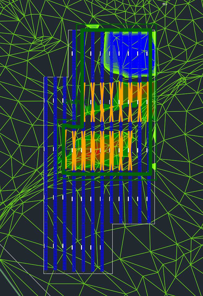
- At first, you need to select a group of trackers that should be used for grading. Below, the trackers inside the red frame get added. The orange trackers for cut operations and additional trackers at the northern end for fill operations.
| For a single grading zone, all trackers must be neighbors with a maximum distance of 2.5 m between them. The row distances are not limited. |
- The result is a single grading zone. There can be multiple grading zones for a field, e.g. when different grading parameters should be used or if PV tables are too far apart according to the already mentioned limitations.
The grading options are initialized with the default orientation distance from the modules to the DTM, the minimum ground clearance as cut parameter and the orientation distance as fill parameter.
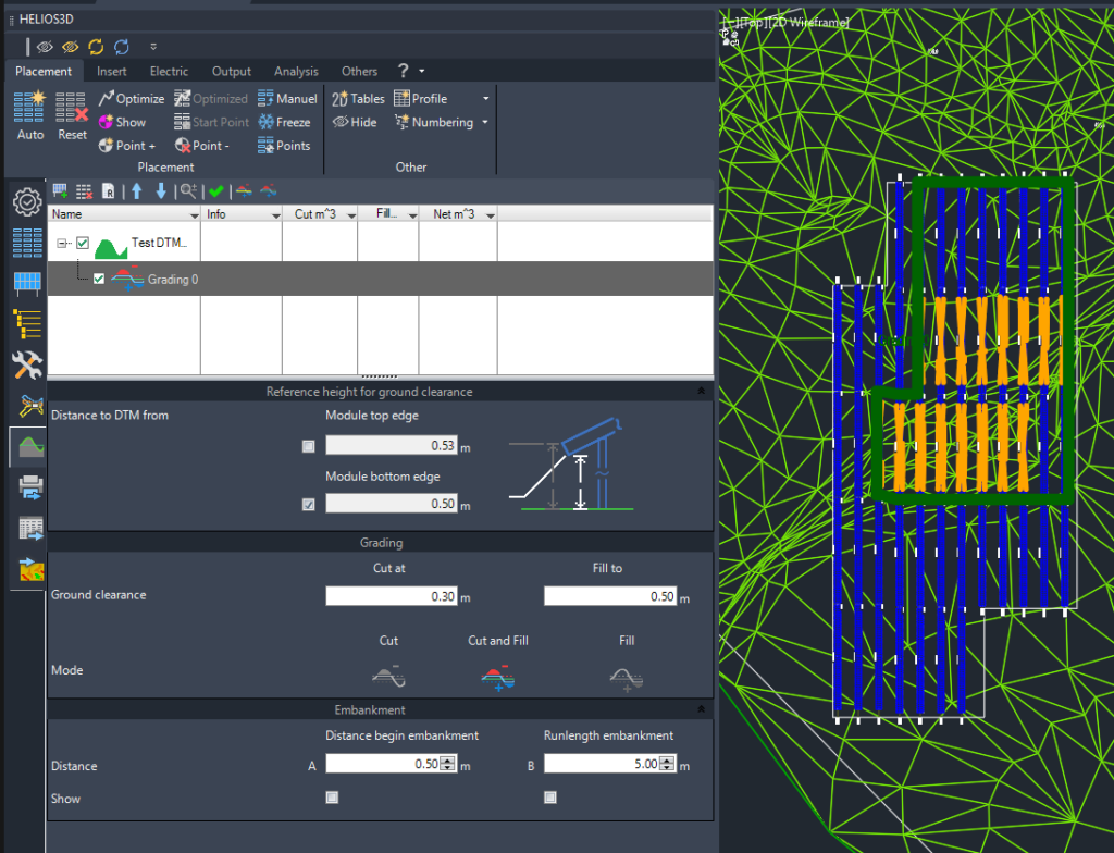
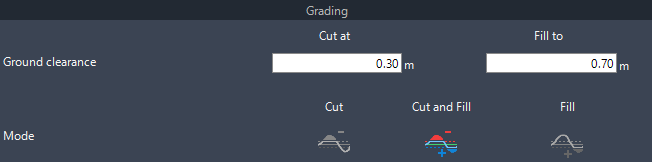
- You can adapt the cut and fill distances measured from the module bottom edges to the surface and choose if you want to just cut, to just fill or to do both at the same time for the grading zone.
The below example cuts surface parts that are closer than 0.3 m from the module back and fill the ground when the distance to the module back is more than 0.7 m.
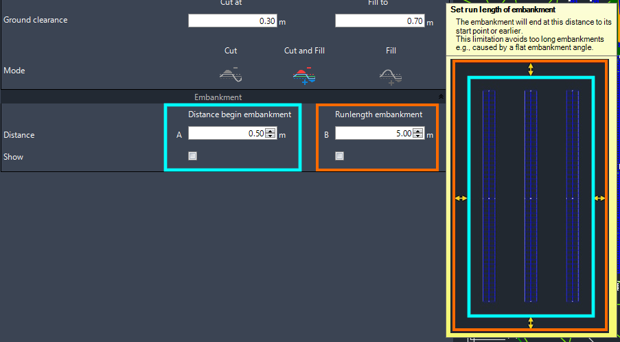
- In the last section, the distance from the reference tracker to start the embankment between the original and the graded surface and the maximum run length for the embankment get set and optionally displayed in the layout with “Show”.
This embankment ensures a realistic alignment to the original surface.
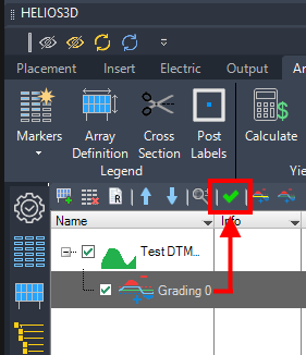
- Then, the grading can be started by „Green checkmark“ and Helios 3D calculates a new surface.
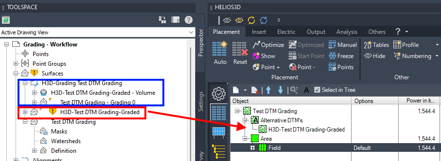
- The placement page shows the new TIN-surface that can be used for future placements, while Toolspace shows the same surface (red marker), which needs to be rebuilt manually, and a collection (blue marker) with TIN-surfaces per grading zone and a volume surface.
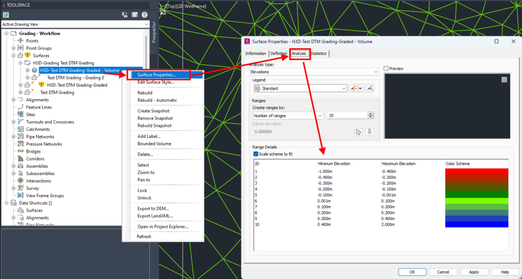
The volume surface is used to create a heatmap with colors from green to red for cut areas and brighter green to blue for fill areas.
You can adjust the color scheme on the Analysis page of the volume surface.
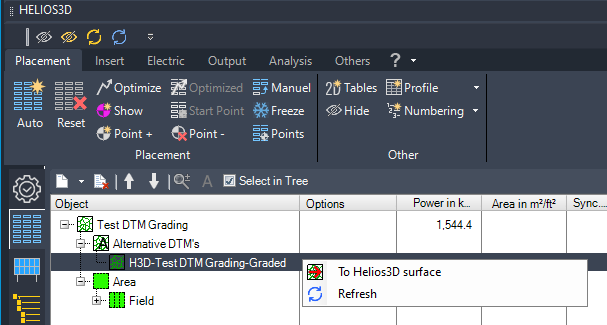
- You can make the graded surface being used for the next placement with right-click to the current surface and the command “To Helios3D surface”.
The command will reset the current placement.
- The new placement on the graded surface should show no conflicts anymore or at least a significant reduction of issues, if grading and placement options contradict each other or in case accuracy limits are reached.
Helios 3D doesn’t consider discrepancies < 10 mm.