
Electrical Structure Page
The Electrical Structure tab provides an overview of the electrical hierarchy and cable information in the current drawing. It helps users inspect connected devices, review cable types and lengths, control the visibility of cable layers, and visually trace module-to-device relationships in the layout.
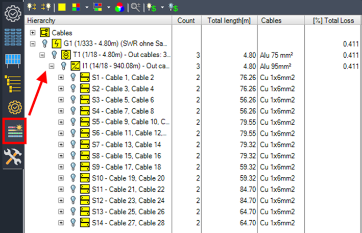
On the Electrical Structure tab, you can view a cable list and toggle the visibility of layers for cables connected to the selected electrical device. For each cable, you can find details such as the number, length, and specific type.
The following tools control how electrical connections and related objects are displayed in the drawing. They are mainly intended for visual inspection, checking connected modules and devices, and making electrical structures easier to understand during review.
Show/hide all outgoing cables

This option shows or hides the outgoing cables of the selected entry.
Show/hide all ingoing cables

Shows or hides ingoing cables of the selected entry.
Show modules

This option shows all modules connected to the selected object in the same color.
Show modules of devices

This option shows all modules connected to the selected object in the same color. When multiple objects are selected, a separate color is used for each object and its connected modules.
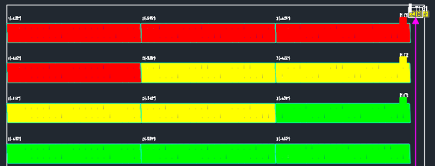
Show modules of parallel devices

This option shows all modules connected to the selected object in the same color. If the object has parallel connected objects with the same parent (e.g., string inverters sharing the same transformer), a separate color is used for each parallel object and its connected modules.
Change color

This option changes the color for the selected entry.
Zoom to object

This option zooms in on the selected object.

This option shows or hides the colors on modules indicating the maximum loss of a module string, array, or inverter.
The structure tree groups cable and device information so that users can inspect the electrical structure from different perspectives. Cable-related entries summarize used cable types and lengths, while device-related entries help control the visibility of cables connected to selected electrical devices.
Cables Node
This lists all cable types used in the drawing, including their total length.
G1 – Grid Node
This lists any device used in the structure tree, allowing you to toggle the visibility of layers for individual cables or for all cables connected to the selected electrical device. If multiple grid connections are used, there will be more than one grid tree listed.