
Project Management
In project management, you can create your projects and organize them within an editable folder structure. Additionally, existing projects can be edited.
Project Management is the central starting point for organizing PV planning projects in Helios 3D. It connects project master data, project directories, drawings, DWG files and project-related evaluation data. Before layout planning, electrical planning or output generation can be started, a project and at least one drawing should be created and assigned correctly.
Use this area to structure projects in folders, maintain project information, create or edit drawings and define which drawing provides the project-relevant evaluation data. This is especially important when a project contains several drawings, layout variants or planning stages.
The following graphic illustrates a sample layout of such a project folder structure and some projects.
The available context menu commands depend on the selected object and the current view. Some commands act on project folders, while others act on selected project records. Before using commands such as Delete, Cut, Paste, Export or Import, verify that the correct project or folder is selected.
Project records may be connected with drawings, project directories and evaluation data. Changes in Project Management can therefore affect the organization of project files and the availability of project-related information in later planning steps.
The project list can be managed in the current view using the following context menu.
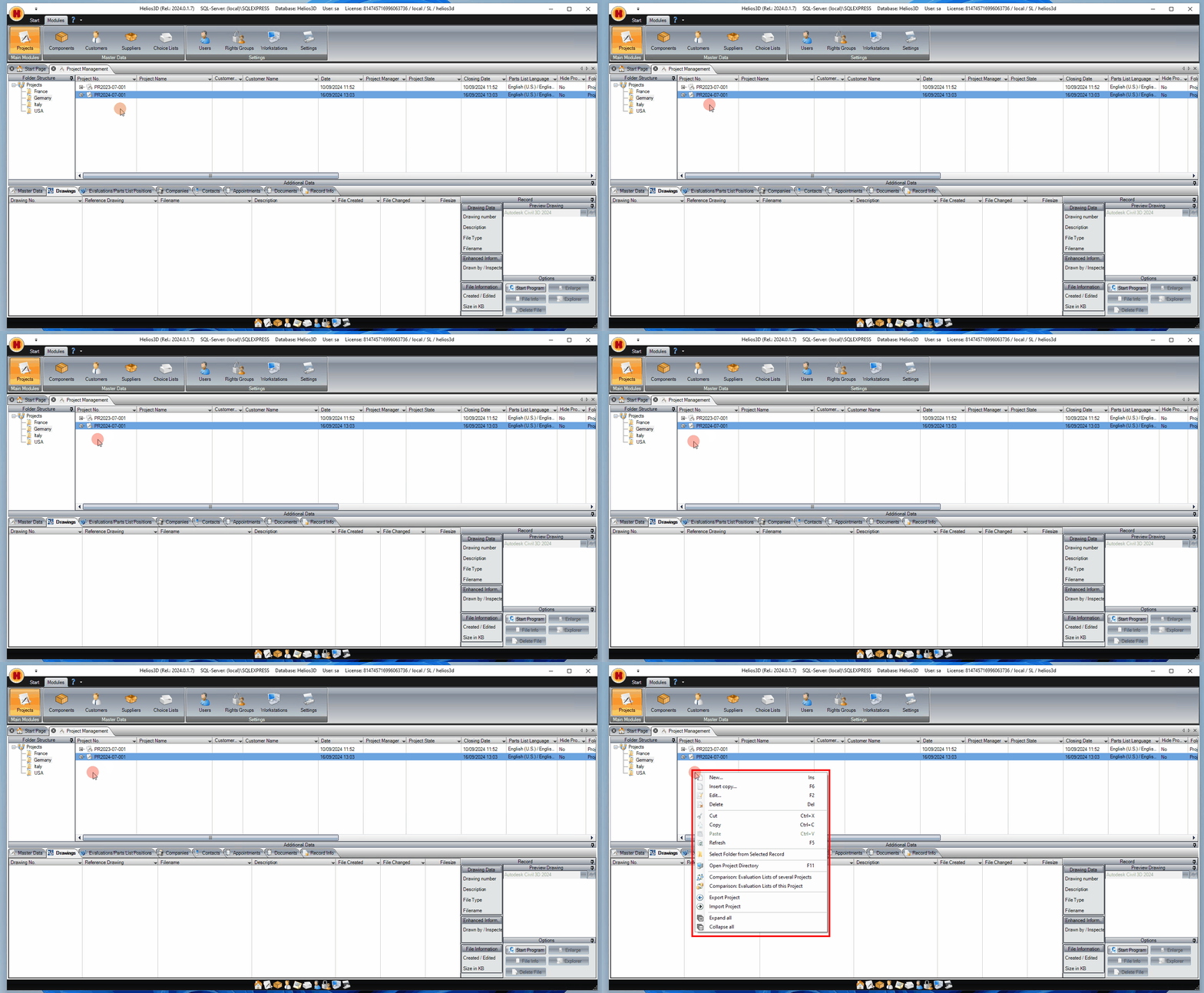
New…
Opens the dialog for creating a new project.
Insert Copy…
Inserts a copy into the project list and opens the dialog for creating/changing a project. The name of the copy must be changed, but modifying other available options is optional.
The copy does not include records linked to the original project, such as drawings.
Edit…
Opens the dialog for modifying the settings of the selected project (the dialog is the same as for creating a project).
Delete
Deletes all selected projects and the data they contain, including all associated drawings, without any additional prompt!
Warning: Deleting a project can remove project data and associated drawings. Before deleting a project, make sure that the project is no longer required and that all required DWG files, exports or project backups are available. This action should only be performed by users who understand the consequences for the project database and file structure.
Cut
Functions like the Windows cut feature, where an element is copied to the clipboard and deleted when pasted.
Copy
Functions like the Windows copy feature, copying an element to the clipboard.
Paste
Functions like the Windows paste feature, pasting an element from the clipboard.
Refresh
Refreshes the project list.
Select Folder from Selected Record
When elements (projects) from multiple nodes are displayed in the current view, you can select an element and use this function to select the corresponding node in the structure tree. This also refreshes/filters the project list.
Open Project Directory
Opens the project directory of the selected project in Windows Explorer.
Comparison: Evaluation Lists of several Projects (out of order!!!)
Opens the dialog for comparing evaluation lists of multiple projects.
Comparison: Evaluation Lists of this Project (out of order!!!)
Opens the dialog for comparing the evaluation lists of the selected project. This dialog is similar to the one for comparing several projects but with pre-filled settings for the selected project.
Project Export/Import
Project export and import are intended for transferring project data between Helios 3D databases or work environments. This can be useful when projects need to be exchanged between workstations, departments, support teams or separate installations.
Before importing a project, check whether the target database already contains projects, drawings, components or article data with similar names or identifiers. Imported project data should be reviewed after the import to confirm that the project structure, drawing references and relevant project information are available as expected.
Project management now includes a new export and import function, enabling the exchange of item data between different databases via an XML file.
The previous import function for project exports from earlier versions remains available. To use it, hold down the Ctrl key when selecting the import function.
To start an export, simply right-click a folder entry, as shown below.
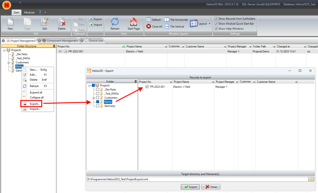
The export always generates a ZIP file containing the drawings and an XML file. The XML file allows Helios 3D to read the project structure and configuration.
The XML file contains the project structure and configuration information used by Helios 3D during import. The ZIP file contains the corresponding drawing data. Both files belong together. If the ZIP file is missing, renamed or stored in another folder, the import may not be able to restore the complete project content.
Component and article data embedded in DWG files may require additional manual steps after import. After opening an imported drawing, verify whether the required component and article information is available in the local database.
The import command requires only the XML file to be selected. However, the corresponding ZIP file must be in the same folder, as shown in the image below.

Component and article data are embedded within the project’s DWG files and must be manually exported from within a drawing to the local Helios 3D database.
Additional Data
Below the project list, there is „Additional Data“ for the selected project. This data is divided across several tabs, which are explained in the subsections below.
Since the Master Data and Record Info tabs only provide an overview of the project data, they do not need further explanation.
Creating a Project
Before creating a project, decide where it should be stored in the folder structure and which project directory should be used. A clear project number, project name and directory structure help to keep drawings, exports, evaluation results and support cases traceable.
For PV projects, the project record should contain enough information to identify the site, customer, project manager and planning context. This improves later reporting, drawing management and project comparison.
If you want to create a project directly in a specific folder, first select that folder in the folder structure.
A project is created by right-clicking in the project list and selecting the menu item „New…“. This will open the dialog shown below.
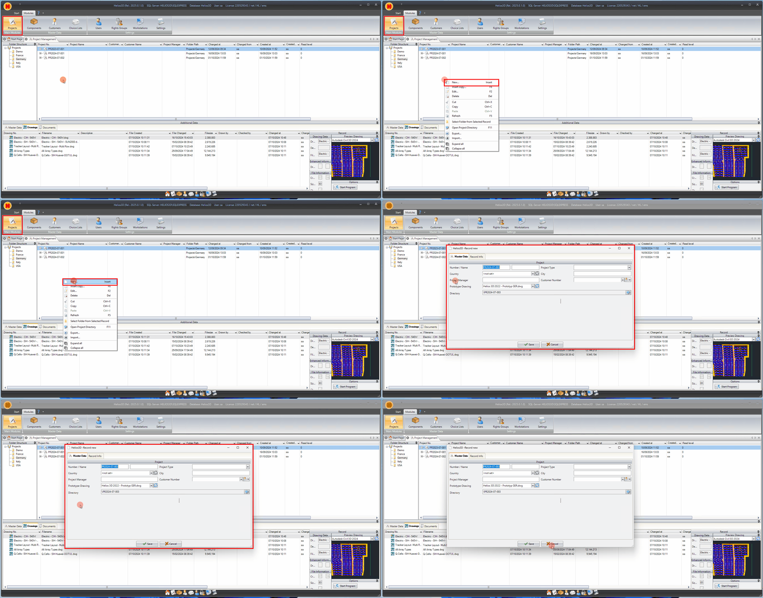
Project Number:
You can enter a project number with up to 32 characters, unless it is managed automatically (if the option „Automatically manage project number“ is enabled in the system settings).
Project Name:
You can enter the project name with up to 64 characters.
Project Type:
Select a project type from the list (optional).
Country:
Select a country from the country list (optional).
Location:
Enter a location (optional).
Project Manager:
Enter a project manager (max. 64 characters) (optional).
Customer Number:
Select a customer from the customer management (optional).
Prototype Drawing:
Here you can select a prototype from the list that will be suggested by default when creating a new drawing.
The selected prototype drawing can speed up the creation of new project drawings by providing a predefined drawing basis. This may include drawing settings, standard structures or prepared content depending on the configured prototype. The available prototype drawings and their exact content depend on the local Helios 3D configuration and should be maintained by an administrator or responsible CAD coordinator.
Directory:
Here you can change the path for the project directory.
Drawings Tab
Drawings are the working files in which the actual PV layout, terrain-related planning, array placement and electrical planning are carried out. In Helios 3D, a project can contain one or more drawings. Each drawing should be named clearly so that users can distinguish between layout variants, planning stages or discipline-specific files.
Creating a drawing entry in the database does not necessarily mean that the DWG file already exists in the project directory. The drawing file is created when the drawing is launched from Helios 3D, as described below.
In this list, you can create and manage drawings for the selected project. A context menu of the drawing list is available for this purpose.
When a new drawing is created in the database application, the corresponding DWG file must be generated by launching the drawing from within Helios 3D. Only then are the drawing files created in the project directory. To start a drawing with the Helios 3D palette included, Helios requires a program configuration for the corresponding version of AutoCAD Civil 3D. The setup is described in the installation guide.
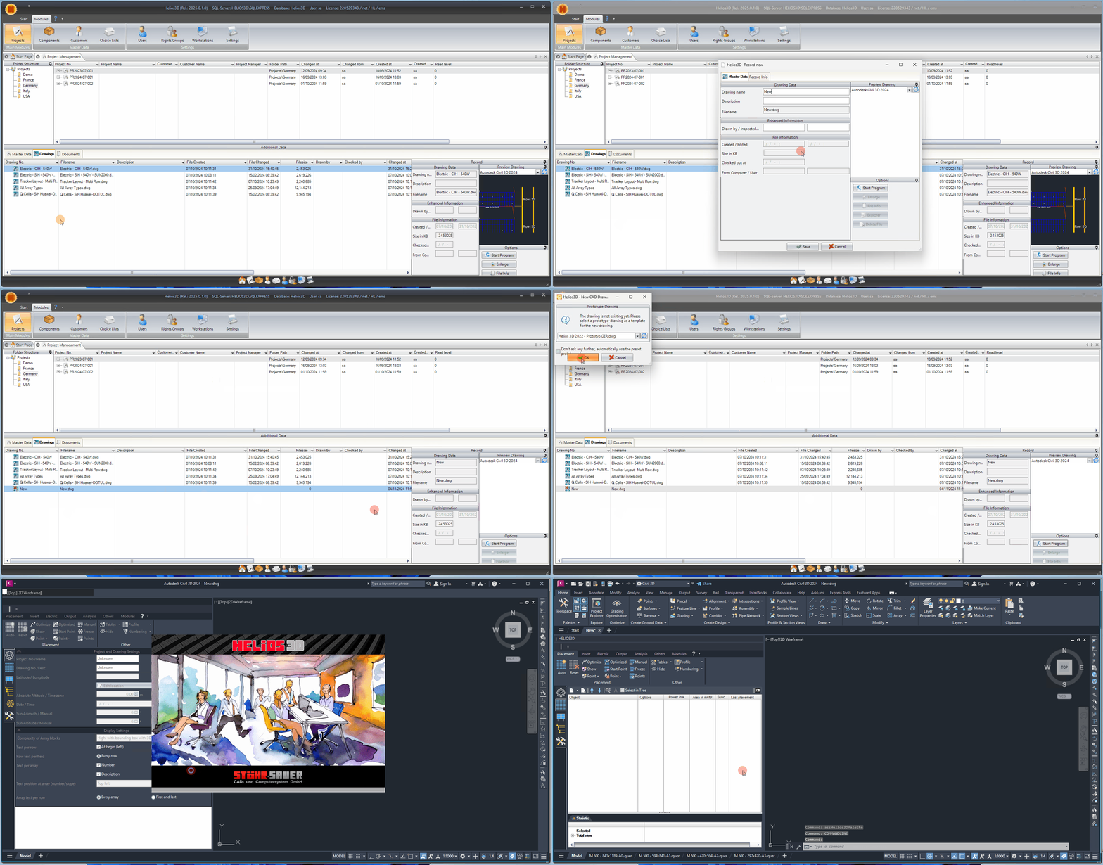
Drawing Master Data
In this section, you can enter all essential master data required for the drawing. The only mandatory field in the dialog below is the „Drawing number“ (the file name without its extension). Additionally, each project should include a designated reference drawing, as only this drawing will transfer its parts list information (such as the number of arrays, project wattage, and similar details) to the project record.
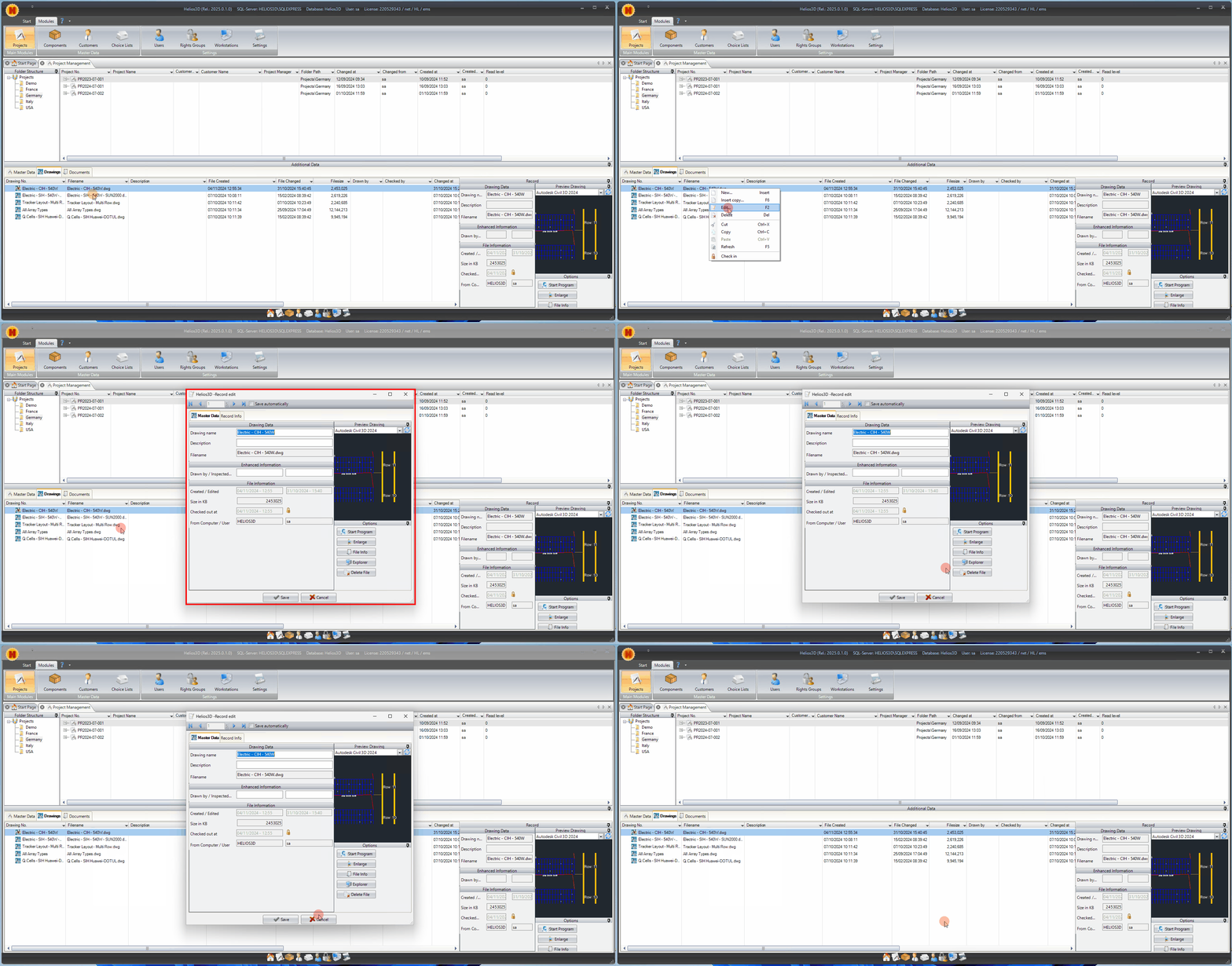
Drawing Number
The drawing number typically corresponds to the drawing name without the file extension. If the „Set Drawing Filename Equal to Drawing Number“ option is enabled in the system settings, the filename is automatically populated. The drawing number and filename are the only required fields.
Description
You can enter a description for the drawing here.
File Type
Here, you can select a file type. The only relevant option is „AutoCAD Drawing.“
Filename
If the „Set Drawing Filename Equal to Drawing Number“ option is enabled in the system settings, this entry will match the drawing number plus the file extension. This is the default setting.
Drawn by / Inspected by
Here, you can enter the names of the drafter and the inspector.
Reference Drawing
Reference drawings transfer their parts list information to the project whenever a new parts list is generated. This option must be enabled for the calculated values—such as project area, project wattage, the number of arrays and panels, and the count of inverters used—to appear in the master data of the project record.
Use only the drawing that should provide the official project values as the reference drawing. In projects with multiple layout variants, preliminary studies or alternative designs, selecting the wrong reference drawing may cause project master data to show outdated or unintended values.
After generating or updating a parts list, check whether the project record shows the expected values for project area, project wattage, number of arrays, number of panels and inverter count.
Created / Edited
Displays the creation date and the date of the most recent modification of the DWG file.
Size in KB
Displays the file size.
Checked out at
Date and time when a drawing was checked out.
From Computer / User
Computer and user from whom the drawing was checked out.
Check out DWG files from remote servers
The check-out/check-in workflow is relevant when drawings are stored on a remote server or network location. Checking out a drawing copies it to a local working directory so that it can be edited with fewer delays. After editing, the drawing should be checked in again so that the server version is updated and other users can continue working with the current file.
This workflow helps avoid performance problems with large DWG files over slow network connections. It also supports controlled editing of drawings in multi-user environments.
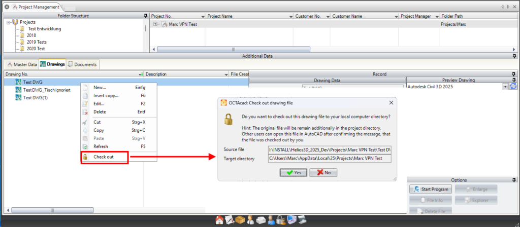
Drawing files can now be checked out from a server, allowing them to be copied locally to:
C:\Users\Username\AppData\Local\25\Projects\Project name
Once checked out, the file can be modified in Helios 3D without delays caused by slow connections. After completing the work, the drawing can be checked back in.
The image below illustrates the check-out procedure. The check-in process follows the same steps and is accessed by right-clicking the drawing entry.
Troubleshooting
If a newly created drawing does not appear as a DWG file in the project directory, start the drawing from within Helios 3D. The DWG file is created only when the drawing is launched from the application.
If the Helios 3D palette does not appear when opening a drawing, check whether the correct AutoCAD Civil 3D program configuration is available for the installed version.
If project values such as project wattage, project area, number of arrays, panels or inverters are missing in the project master data, check whether a reference drawing is defined and whether the parts list has been generated from that drawing.
If a project import fails, verify that the selected XML file and the corresponding ZIP file are stored in the same folder and have not been renamed independently.
If opening or saving drawings on a server is slow, consider using the check-out/check-in workflow for remote DWG files.