
Component Management
Here, you can create or edit components. The functions available here are the same as those described in the following Section, along with our explanations for the array generator.
Component Management is part of the database application of Helios 3D. It is used to maintain component master data that can later be used in array definitions, module tables, electrical planning, reports, and data exchange workflows.
In a typical planning workflow, components should only be edited with care. Changes to component data do not automatically update existing placements in a drawing. To make changed component values effective in a drawing, the corresponding array definition must be regenerated in the Array Generator and, if required, the existing placement must be overwritten.
For the standard workflow, we assume that all components will be created and typically edited within the „array generator“. This is necessary because, for any component to be used in a drawing, or for any changes to take effect in that drawing, the array definition must be regenerated in the array generator and, if necessary, an existing placement must be overwritten. Components required for the Electric module are detailed in Section „Electric“.
The following image shows the basic dialog for creating a new component.
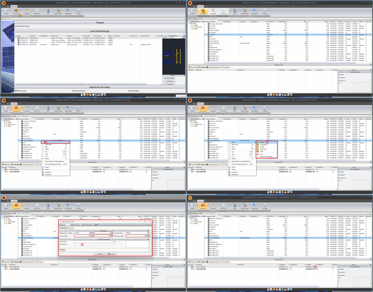
New Record / Component
Before creating a new component, make sure that the required manufacturer, component folder, and component type are available in the database. The component number should be unique and should follow the naming convention used in your company or project database.
Component data should preferably be entered from the official manufacturer data sheet. This is especially important for PV modules, electrical devices, cables, transformers, and components that are later used for calculations, electrical checks, bill of materials, or yield assessment.
This section outlines the master data that is consistent across all components in the database. This includes fields such as “Main Data,” “Component Languages,” and “Parameters.” Typically, all sections are displayed within a single dialog, but here they are separated for clarity. Most fields are optional, with the exception of the component number, which is required.
Import module data from PAN files
For modules an import button appears at the top of the edit dialog. It opens a dialog for selecting a file with the extension “.pan” for reading the module properties. Those files can be generated with PVsyst, and some module manufactures might offer such files either.
There is no guarantee that a PAN file provides all data Helios 3D requires.
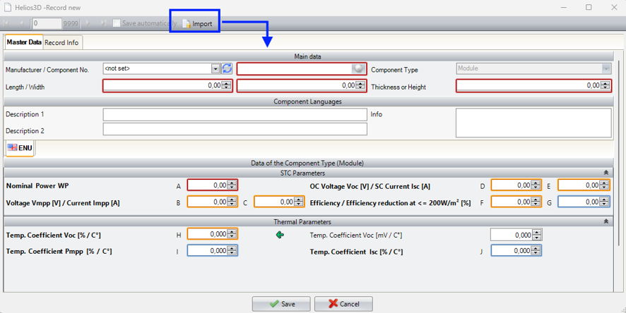
Main Data
The main dimensions of a component are used wherever the physical size of the component is relevant for the planning process. For modules, length, width, thickness, and height can affect table dimensions and the resulting geometry in the drawing.
Always check whether the entered unit system matches the project or database configuration. Incorrect dimensions may lead to wrong table sizes, incorrect placement results, or misleading quantities in evaluations.
Manufacturer / Component Number
Here, you can select a manufacturer from the database and enter a component number.
Component Type
This entry depends on which item is to be created.
Length (mm/in) / Width (mm/in)
Here you can enter length and width both in mm/in. These values are used for calculating the table dimensions.
Thickness/Height(mm/in)
Here you can enter thickness and height both in mm/in. The thickness value is used for calculating the table dimensions.
Component Languages
Description 1
Here you can enter a description in the corresponding language.
Description 2
Here you can enter another description in the corresponding language.
Info
Here, you can enter essential information about the component, such as details on its installation.
Cables
For cables, it is now possible to set the number of phases. Initially, this will determine the number of cable connections between devices in the AC area. The new value is marked in blue in the following figure.
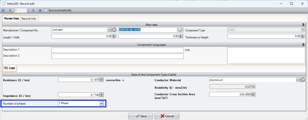
Transformer
The maximum connection power of a transformer is used when adding new devices to check whether another inverter or AC collector can be connected without exceeding the transformer capacity. This check supports the electrical structure workflow and helps avoid overloads during device assignment.
Please note that the page states an important limitation: if the input power of an already connected inverter is increased later and this causes an overload, this is not checked automatically. Users should manually review the Electrical Structure List after changing connected devices or electrical component data.
The maximum connection power can now be specified in a transformer’s data sheet. When adding a new device, the system verifies whether an additional inverter or AC collector can be connected to the same transformer without exceeding its capacity.
However, if the input power of an already connected inverter increases and causes an overload, this will not be checked.
The transformer load is displayed in the Electrical Structure List, just like for inverters. The image below highlights the new entry in blue.
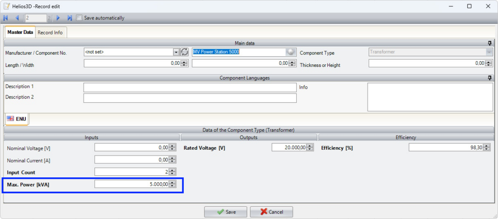
Electrical Grid Connection
Starting with Helios 3D version 2026.0.2.0, electrical grid connections are managed as regular components or articles.
In previous versions, grid connections were stored as entries in the Electrical Grid choice list. The component-based definition provides a consistent workflow for grid connections and other electrical devices.
New grid connections must be created in the Component Management of the Helios 3D database application.
Creating a Grid Connection
Open Component Management and select the appropriate folder for electrical components.
Create a new component and select Grid as the component type. Enter a unique component number and a clear description of the grid connection.

Save the component after checking the entered values. The new grid-connection component can then be selected in the electrical definition and placement workflows.
Grid Connection Data
The grid-connection record contains the general master data of a standard component and the information required for the electrical grid definition.
Check the following information before saving the component:
- component folder;
- component number;
- component type;
- description;
- voltage;
- number of phases;
- project-specific information.
The component number must be unique within the database. Use consistent descriptions and units for all grid-connection components.
Conversion of Existing Grid Definitions
When the first DWG containing electrical content is opened with Helios 3D version 2026.0.2.0, existing grid definitions used in the drawing are automatically created as components or articles.
The original entries in the Electrical Grid choice list are retained. They are not automatically deleted during the conversion.
New grid connections must nevertheless be created as components in Component Management.
After the conversion, verify that every grid connection used in the drawing has a corresponding component record.
Compatibility with Older Versions
Important:
A DWG saved with a component-based grid connection can no longer be edited with an older Helios 3D version that does not support this definition.
Before opening and saving productive drawings with version 2026.0.2.0:
- create a backup copy of the DWG;
- back up the Helios 3D database;
- back up the project and library folders;
- make sure that all project users use a compatible version;
- test the conversion with a copy of the drawing.
Do not overwrite the only available copy of a drawing if it may still be required in an older version.
Checking the Grid Connection
After creating or converting a grid connection, verify that:
- the grid connection appears in Component Management;
- the component type is
Grid; - the component number is unique;
- voltage and phase information are correct;
- the component can be selected in the electrical workflow;
- the drawing uses the intended grid-connection component;
- no unintended duplicate component was created.
New Module Definition
For PV modules, the values from the manufacturer data sheet are the basis for several downstream workflows. STC power and module dimensions are required for current calculations and layout generation. Electrical values such as V_mpp, I_mpp, V_oc, I_sc, and temperature coefficients are relevant for electrical planning and plausibility checks. Yield-related values may be used in later evaluation steps.
If a value is not available in the data sheet, do not enter estimated values without internal approval. Missing optional values may be acceptable for layout work, but can reduce the quality of electrical planning, yield assessment, or later reporting.
For each new module definition, you will be prompted to select a component folder, as shown in the Figure.
Afterwards, you can enter the module’s main data, including Component Description, Component Language, Parameters, and Data of the Component Type (Module). You can also attach an image of the module.
Below, we describe the input fields in the “Data of the Component Type (Module)” dialog section. For standard main data for any component, please refer to section „New Record / Component„.
Only the values in bold are used for calculations in the current version. All other inputs are optional but recommended for future functionality. The module’s measurements and STC power are essential (indicated by a red frame if missing). Values framed in orange are critical for the electric module, while those with a blue frame are important for the yield assessment.
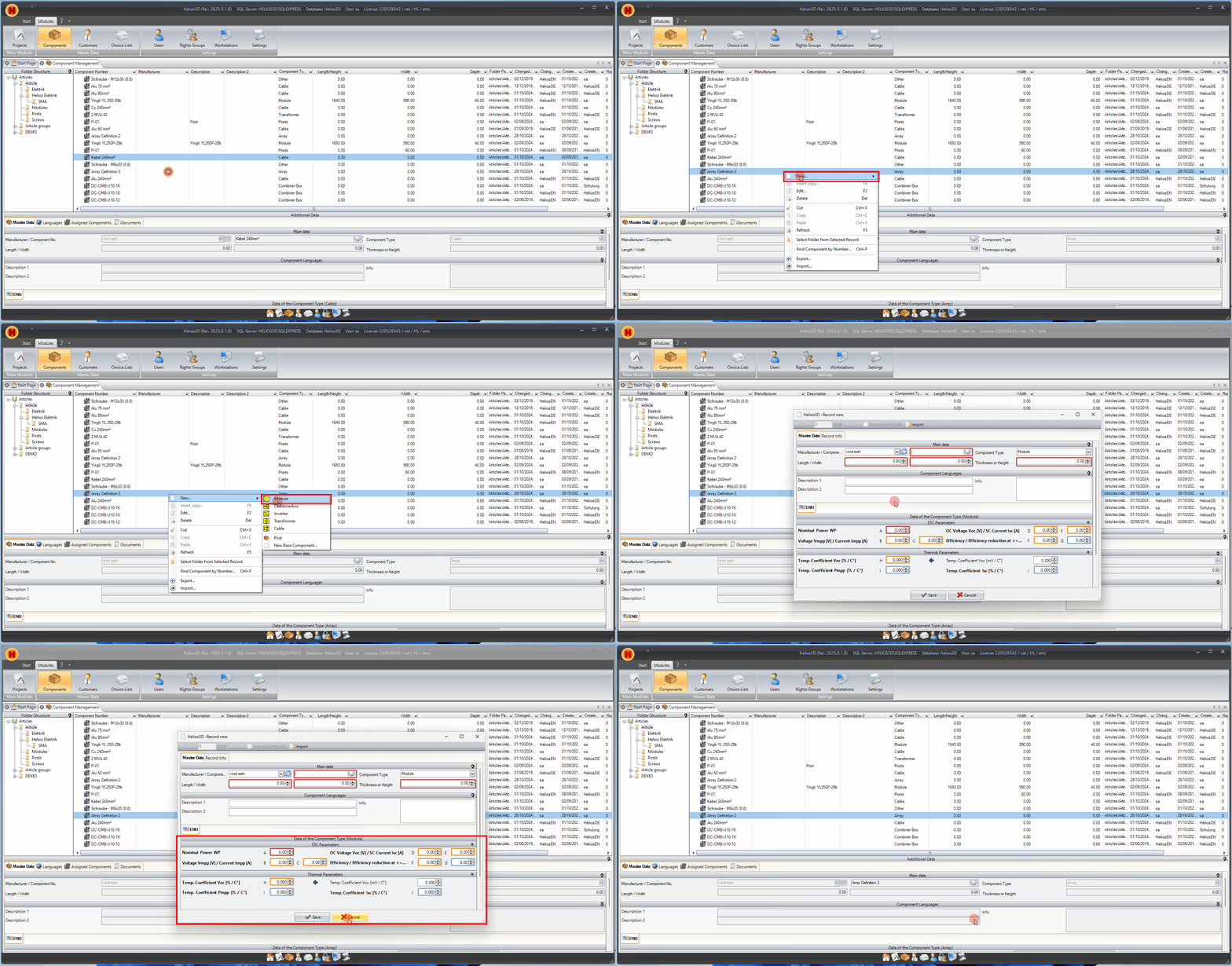
Nominal Power WP
Here you can enter the power of the module for MPP. This value means the peak power at MPP which can be reached by the default conditions with an irradiance of 1.000 W/m², a module temperature of 25°C and an AM (Air Mass) of 1,5.
Voltage Vmpp [V] / Current Impp [A]
Values from the manufacturer data sheet, which means the voltage and the current flow at nominal power of the module.
OC Voltage Voc [V] / SC Current Isc[A]
Values from the manufacturer data sheet, which means the open circuit voltage and the short circuit current of the module.
Efficiency / Efficiency reduction at <= 200W/m² (%)
Values from the manufacturer data sheet, which means the degree of efficiency and efficiency reduction. Efficiency is used for the calculation of electric losses, while the efficiency reduction is only used in yield assessment.
If the reduction value can’t be found, PVsyst once recommended a value around 3%.
Temperature Coefficient Voc [% / C°]
Values from the manufacturer data sheet, which mean the dependency of power
drain for nominal power respectively for open circuit voltage on the temperature.
(power coefficient, voltage coefficient).
Temperature Coefficient Voc [mV / C°]
This value is just used to calculate
the %/C° value and only that value will be saved.

Temperature Coefficient Pmpp [% / C°]
Values from the manufacturer data sheet, which mean the dependency of power drain for nominal power respectively for open circuit voltage on the temperature. (power coefficient, voltage coefficient)
Temperature Coefficient Isc [% / C°]
This value is an inscription of the manufacturer and means the dependency of short circuit current on the temperature. (current coefficient)
New Post Definition
Please enter the default data for each component as outlined in Section „Creating a New Post Geometry.“ Once completed, you can proceed to enter the „Data of the Component Type (Post).“
As shown in the figure below, only post types from the database are available for selection at this stage.
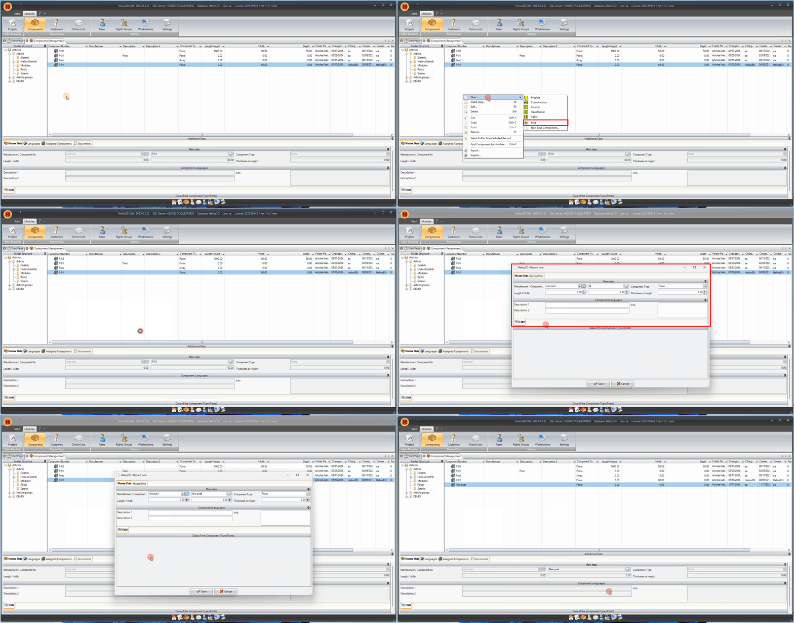
All posts are displayed with the default geometry provided in Helios 3D. To use a different geometry for a post, please create it as outlined in the following subsection.
Creating a New Post Geometry
Post geometry is not defined only by the database entry. If a specific post shape is required in the drawing, a corresponding DWG file must exist in the post library. The drawing name must match the database component number.
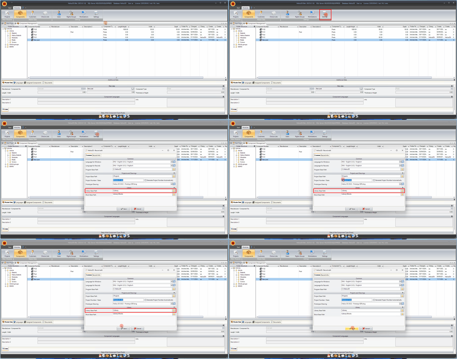
Use the default PostPrototype.dwg as a template and save the new post drawing in the configured library path. The library base path is defined in the system settings of Helios 3D.
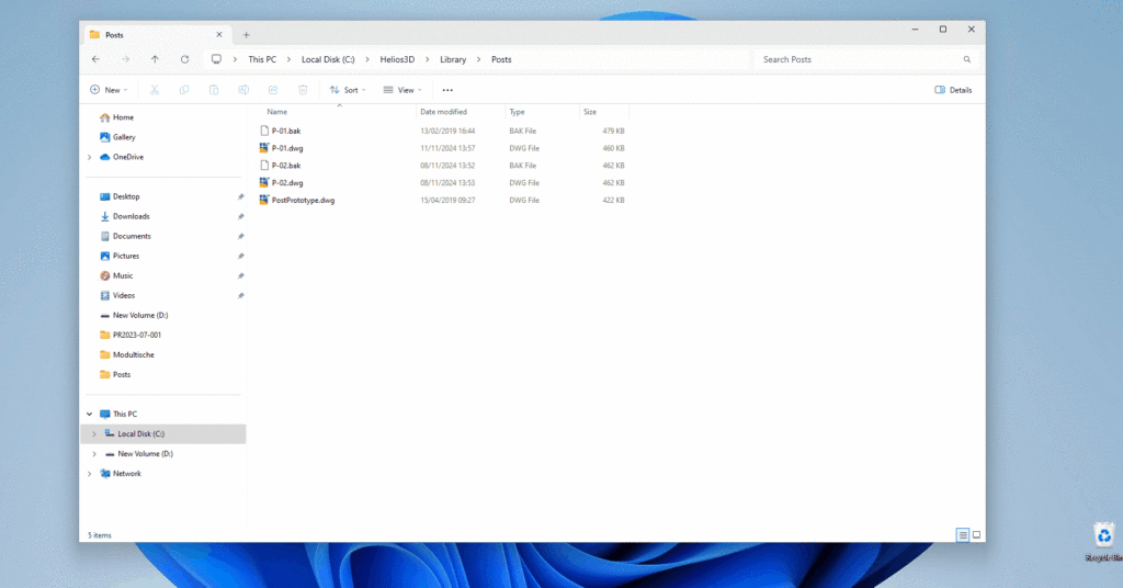
This workflow outlines the process for creating a new post geometry. To do this, you need to create a new post drawing (DWG file) and save it in the “\Library\Posts” folder, using the same name as the corresponding database component.
The location of the library folder is specified in the system settings of Helios 3D.
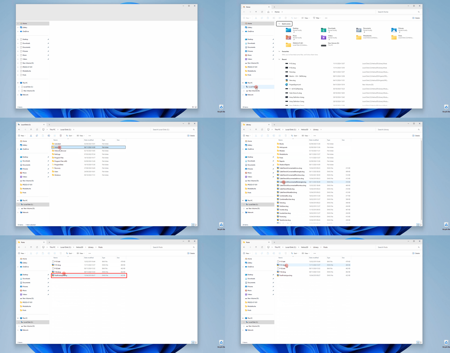
- Make a copy of the AutoCAD file “PostPrototype.dwg” (located in the “\Library\Posts” directory) and rename the copy to match the corresponding database component, using the format: component number.dwg.
| Post Component Number | Drawing Name |
| P-01 | P-01.dwg |
- Open the new post drawing in Autodesk Civil 3D. The drawing area is divided into four views: Top, Left, Bottom, and Perspective.
To work within a specific view, click inside the corresponding frame.
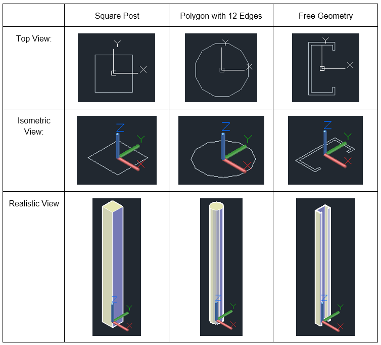
- The final geometry, displayed after placement, is based on the post’s footprint. When inserted into a planning drawing, Helios 3D extrudes the 2D footprint to create the final geometry, which is then placed in the planning drawing with the specified length.
Create the footprint of the post geometry in the top view, positioning it with the base point (0, 0, 0) of the drawing at the center of the footprint.
- Now, draw the footprint around the base point of the post drawing, ensuring that point (0, 0, 0) aligns with the center axis of the post.
Component Export/Import (articles)
The XML export and import functions can be used to exchange component data between different databases. This is useful when component records need to be transferred from a test database to a production database or shared between workstations, teams, or projects.
Before importing component data, check whether the target database already contains components with the same component numbers. The page does not describe conflict handling, overwrite behavior, or version compatibility. These points should be reviewed before using the import function in a productive database.
Strong recommendation: Create a database backup before importing component data.
Component management now includes an export and import function, enabling the exchange of item data between different databases via an XML file.
The export dialog can be accessed through the context menu of the folder structure. In the example below, modules are preselected. Using checkboxes, you can precisely choose which modules to export.
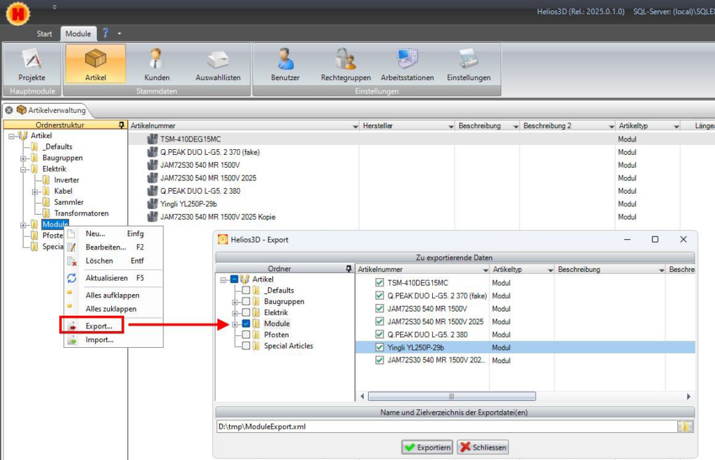
In the row above the <Export> button, the destination path and name of the export file in XML format can be set.
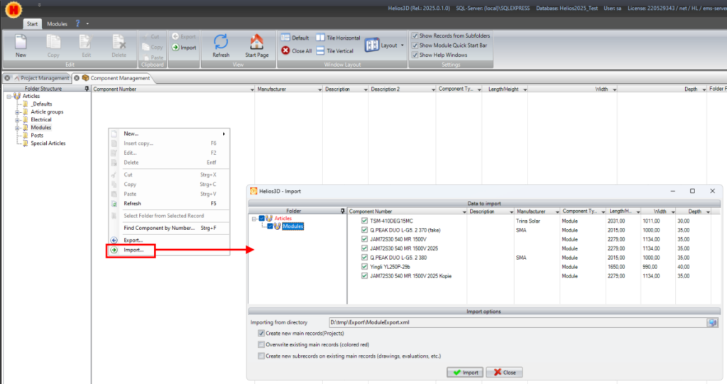
The import function is accessed via the context menu of the item list. After selecting Import, a dialog appears for choosing the XML file, from which the contained data is loaded.
In the illustration below, you can select the modules you want to import by checking the corresponding boxes.
Troubleshooting and common checks
If a new or changed component does not appear in the expected workflow, check whether the component was created in the correct folder and with the correct component type. Also verify whether the corresponding array definition has been regenerated in the Array Generator.
If changed component values are not visible in an existing drawing, the drawing may still contain an older placement based on the previous array definition. Regenerate the array definition and overwrite the existing placement if necessary.
If a post geometry is not displayed as expected, check whether the DWG file is stored in the configured \Library\Posts folder and whether the file name matches the component number exactly.
If imported components are missing after an XML import, check whether the correct XML file was selected, whether the intended components were checked in the import dialog, and whether the target database accepts the imported component type.