Grading Function
The grading function enables modification of the surface by cutting specific areas and optionally filling others, based on the distances to the racks of an existing PV layout. This process creates a new, graded surface beneath the selected arrays, eliminating the need to lift arrays to achieve a specific clearance.
Use this function when the PV layout should remain geometrically unchanged while the terrain surface is adapted below the selected arrays. The grading workflow is intended to create an alternative graded surface from selected array groups and then use this surface for further placement work in Helios 3D.
Starting with version 2024, fixed-tilt arrays and trackers are supported; however, east-west racks are not included.
Requirements for grading
Before starting the grading workflow, create the PV layout on the original DTM without height adjustment for arrays that have a module-DTM clearance conflict. This is required so that the graded surface can later reproduce the original placement geometry.
To ensure the placement on the new surface matches the original layout, a PV layout must be created without any height adjustments to arrays that have a module-DTM clearance conflict.
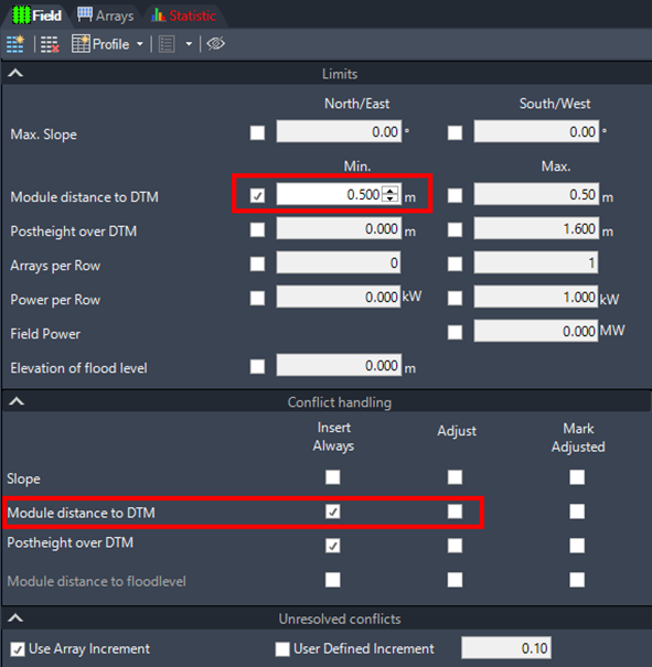
In the placement options, configure the module distance to the DTM and select the “Insert Always” option while leaving “Adjust” unchecked. This ensures that the original layout remains unchanged, even in cases of clearance conflicts.
Do not activate automatic adjustment for this preparation step. The purpose is to keep the original array layout unchanged, even where the defined module-DTM clearance is not met.
For example, if the array height is set to 0.8 m in the array definition, and the module-DTM distance is configured to 0.50 m, the layout will maintain these specifications without adjustments.
Create Grading Zone
The grading function, found under the Tools menu, requires the user to select a group of arrays. These arrays must be directly adjacent to each other. If the arrays are farther apart, you will need to perform multiple grading operations sequentially.
If the required arrays are not directly adjacent, create separate grading zones and run the grading operation for each group one after another.
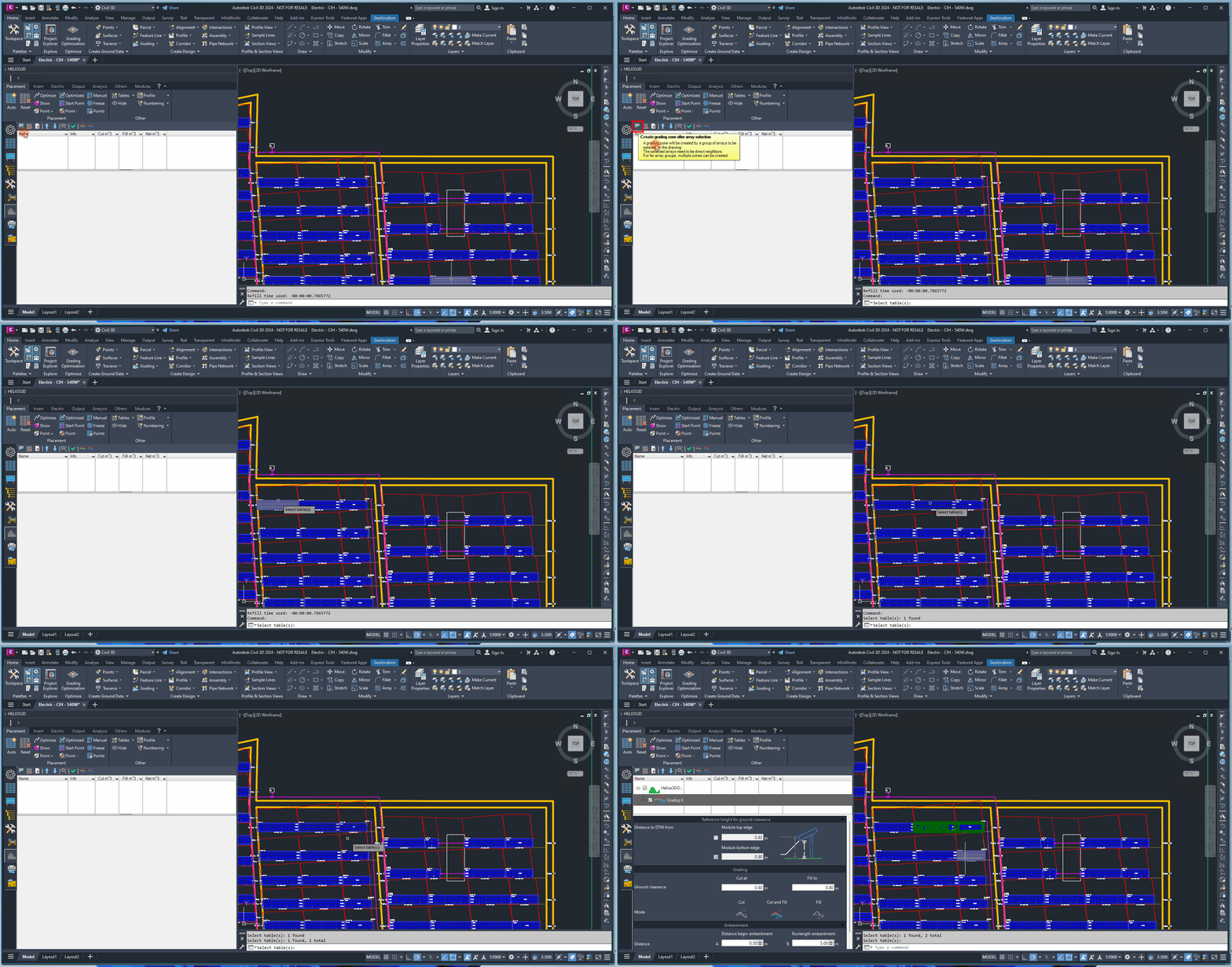
Each group of arrays forms a separate grading zone, similar to islands, which are then integrated with the original surface. In the example below, a pair of arrays is shown, with the first array selected for grading.
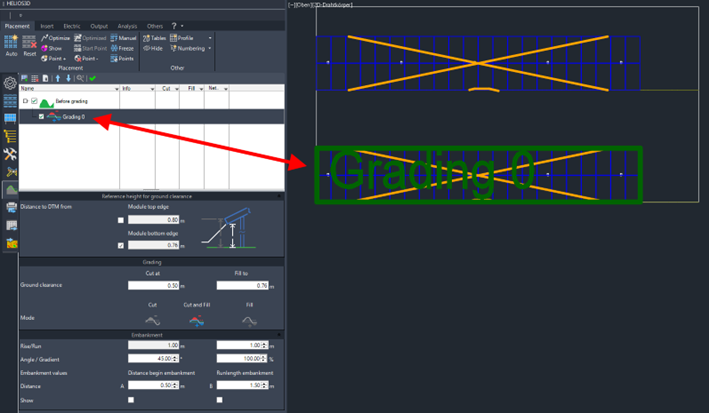
For eachgrading zone you can set the below options for the graded surface.
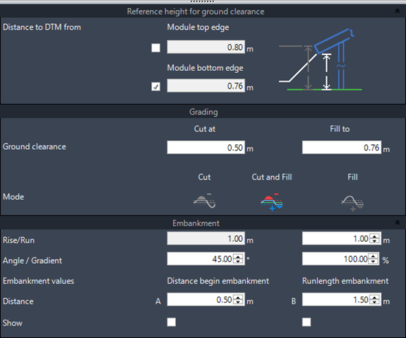
The following settings define how the selected grading zone is converted into a graded surface. They control the reference edge, clearance distance, cut/fill mode and embankment transition to the original surface.
Distance to DTM From
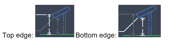
The cut and fill distances are measured from either the top or bottom edge of the module. These values are determined by the array definition properties and cannot be modified here.
The preview on the right visually indicates the selected edge, highlighted in white.
Ground Clearance
Set the distance for cut and fill operations. Areas closer than the specified distance will be cut, while areas further away will be filled.
Mode
You can choose from the following options:
- Cut Only
- Fill Only
- Cut and Fill (both operations performed simultaneously)
Select “Cut Only” if only terrain above the required clearance should be removed. Select “Fill Only” if only terrain below the required clearance should be raised. Select “Cut and Fill” if both operations should be performed in the same grading run.
Embankment
An embankment is created to smoothly transition the grading zones with the original surface. The Rise is fixed at 1 meter, and the Run can be adjusted to calculate the Angle and Gradient. When either the Angle or Gradient is changed, the other value, along with the Run, is automatically recalculated.
Distance to Begin Embankment
Set the starting distance from the arrays to ensure the embankment edge doesn’t align directly with the array edges.
Run Length of Embankment
Limits the maximum length of the embankment to prevent overly long transitions, which can occur if the angle is too shallow.
Show
Displays temporary polylines that represent the set distances for the embankment, providing a visual reference for the grading layout.
Create Grading Surface
The grading surface is generated based on the selected zones, integrating the cut and fill operations to create a smooth, adjusted surface beneath the arrays.
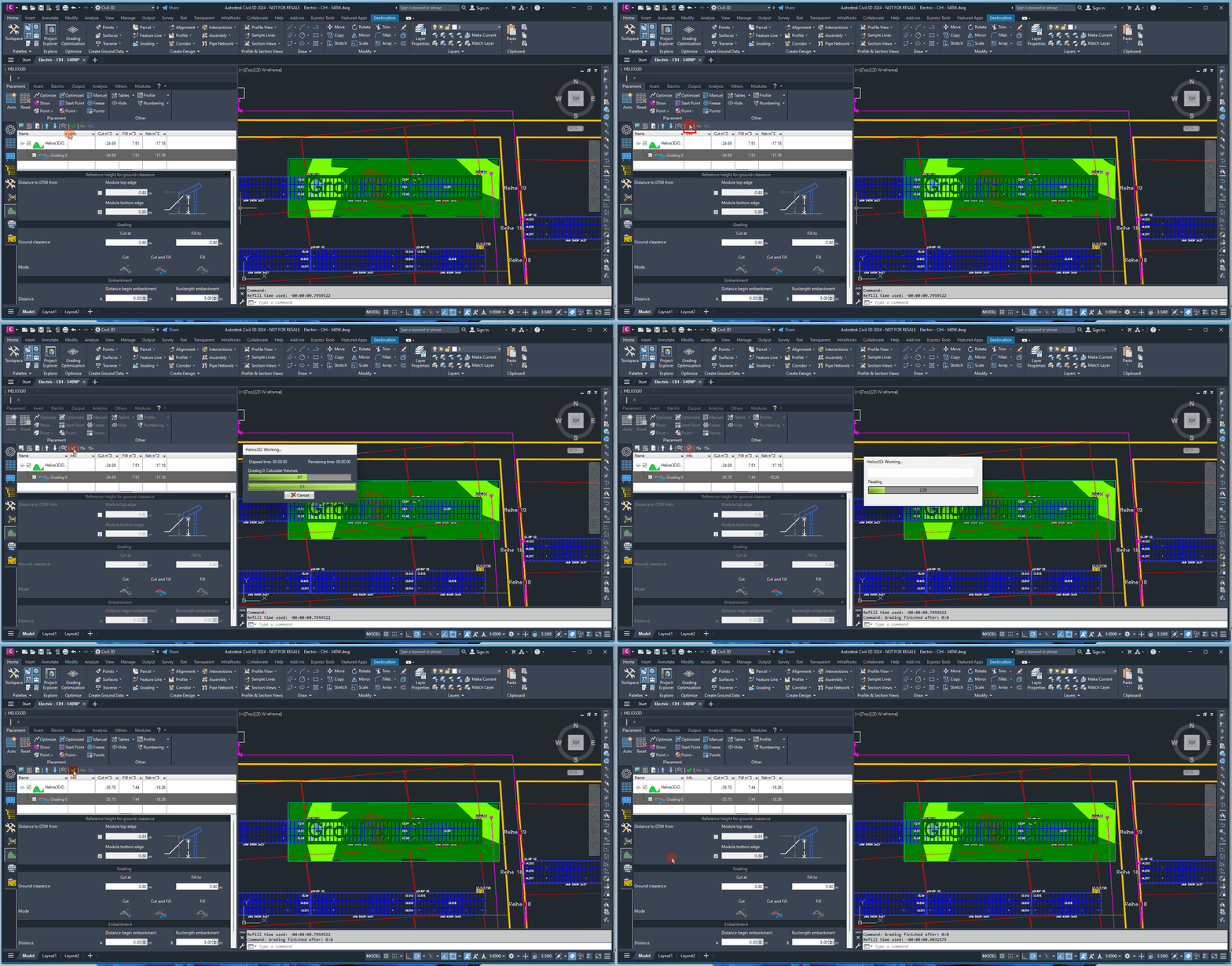
After the grading zones and parameters have been defined, run the grading process to generate the adjusted surface. The result is an alternative TIN surface that can be used for subsequent placement work.
The generated surface is a standard TIN (Triangulated Irregular Network) surface, which is displayed in both the Autodesk Civil 3D Toolspace and the placement list of the Helios 3D palette.
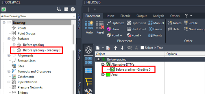
Review the generated surface before assigning it as the active Helios 3D surface.
The graded surface can be set as the Helios3D surface, which will reset the existing PV layout. To do this, right-click on the graded surface in the context menu and select the „To Helios3D surface“ command.
Note:
Setting the graded surface as the Helios 3D surface resets the existing PV layout. Use this command only when the graded surface is intended to become the basis for the placement.
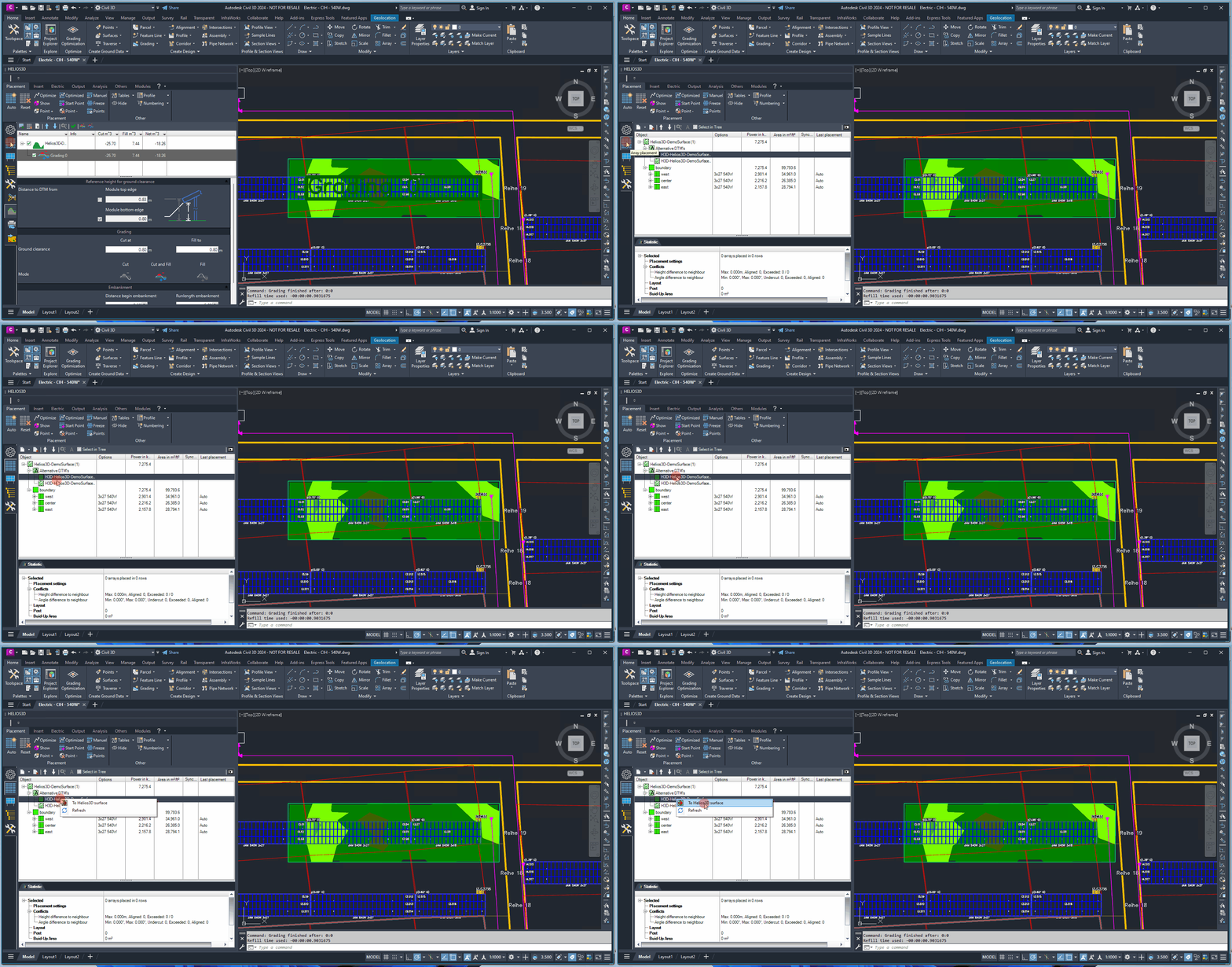
Now placements use the graded surface and the original is displayed as alternative DTM.
Grading reference edges for tracker arrays
For tracker layouts, grading depends on reference points created during tracker insertion. These reference points are used to keep the tracker orientation consistent with the graded terrain.
For tracker layouts created in earlier program versions up to 2024, the placement must be renewed to ensure that the orientation of each tracker is maintained relative to the graded terrain.
For detailed information on how trackers are rotated to align with the ground, please refer to section „Insertion/rotation of a tracker array to the surface“.

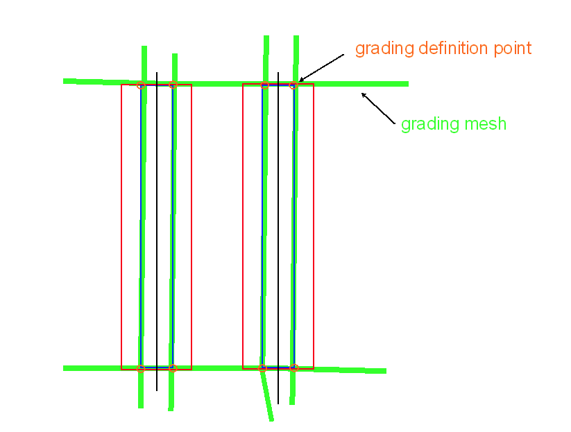
The grading surface (represented in green) is created using the two reference points at the beginning and end of the tracker, which are established during the tracker insertion. A planar surface is then generated between the rows, connecting these tracker reference points. The distance for cut and fill can be set individually based on the module’s bottom edges.
The grading reference points correspond to 3D coordinates located beneath the lowest module points at the start and end of the tracker. This ensures that the tracker placement on the graded terrain remains consistent with the original layout.