
Array Drawing
The Array Drawing settings describe how the table geometry of an array definition is represented in the drawing. In Helios 3D, this drawing is primarily a symbolic representation of the inserted array parameters and is intended to support placement, checking, and further layout work.
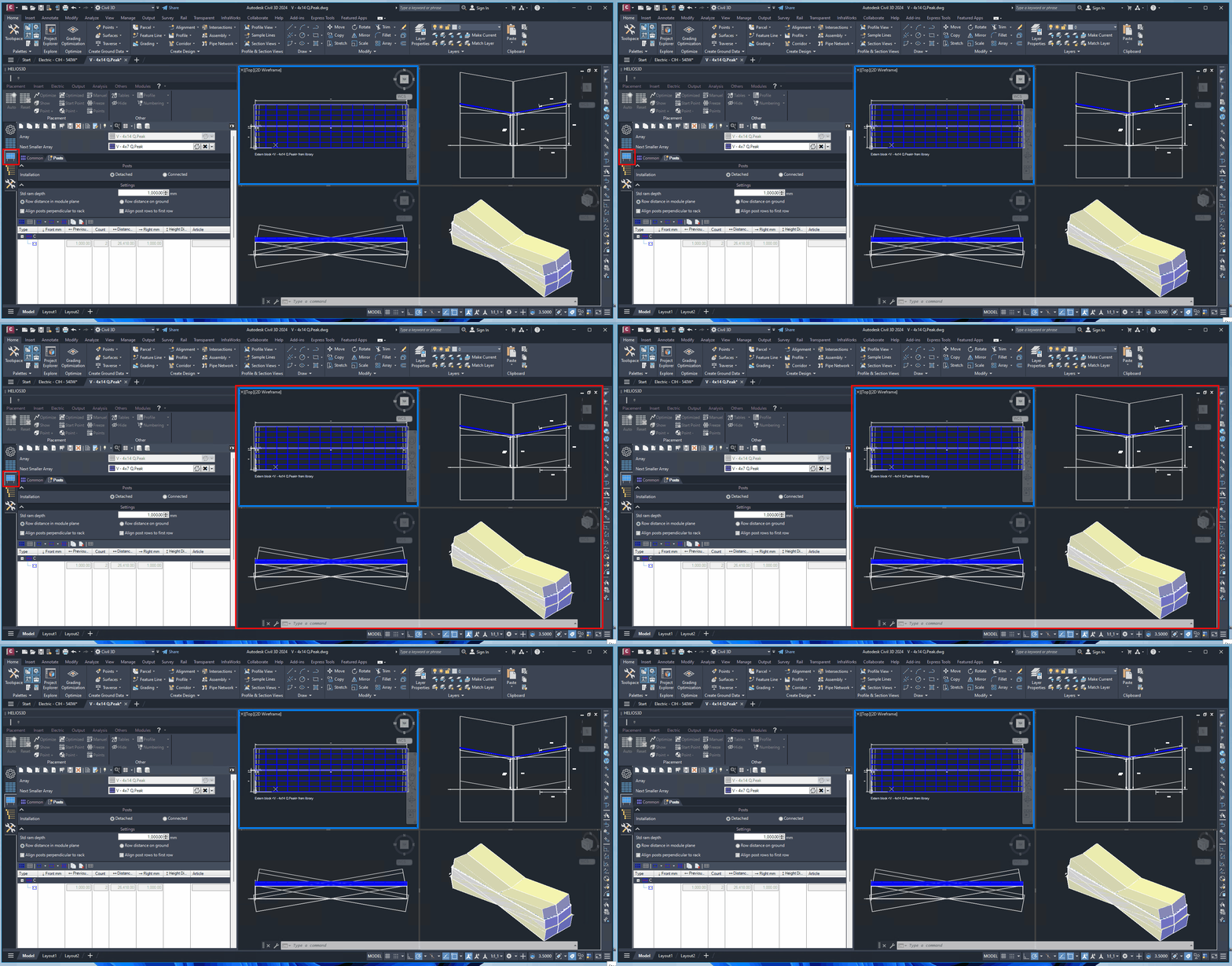
The drawing of the table features a symbolic representation of the inserted parameters. For a more realistic geometry of the array, suitable for presentations or renderings, you can create detailed models using AutoCAD functionality. Afterward, you can use reference points to insert the geometry into your drawing via the block import function. This block will then be available for future placements within the project.
For presentation purposes or renderings, a more detailed geometry can be created with AutoCAD functionality and inserted into the drawing as a block. This approach is useful when a visually realistic representation is required, but it should be distinguished from the parameter-based symbolic table drawing used for array definition and placement.
Please note that in this case, there will be a fixed pitch for all tables, as the variable pitch functionality cannot be utilized within a block.
Important:
When detailed geometry is inserted as a block, the pitch is fixed for all tables that use this block. Variable pitch functionality cannot be used inside the block. Use this method only when a fixed-pitch representation is acceptable for the intended layout, presentation, or rendering purpose.
Recommended Use
Use the symbolic array drawing when the focus is on parameter-based layout work and array placement. Use a detailed AutoCAD-based block only when a more realistic visual representation is required, for example for presentation or rendering workflows. Before using a block-based geometry, check whether the fixed pitch limitation is acceptable for the project.
Visibility
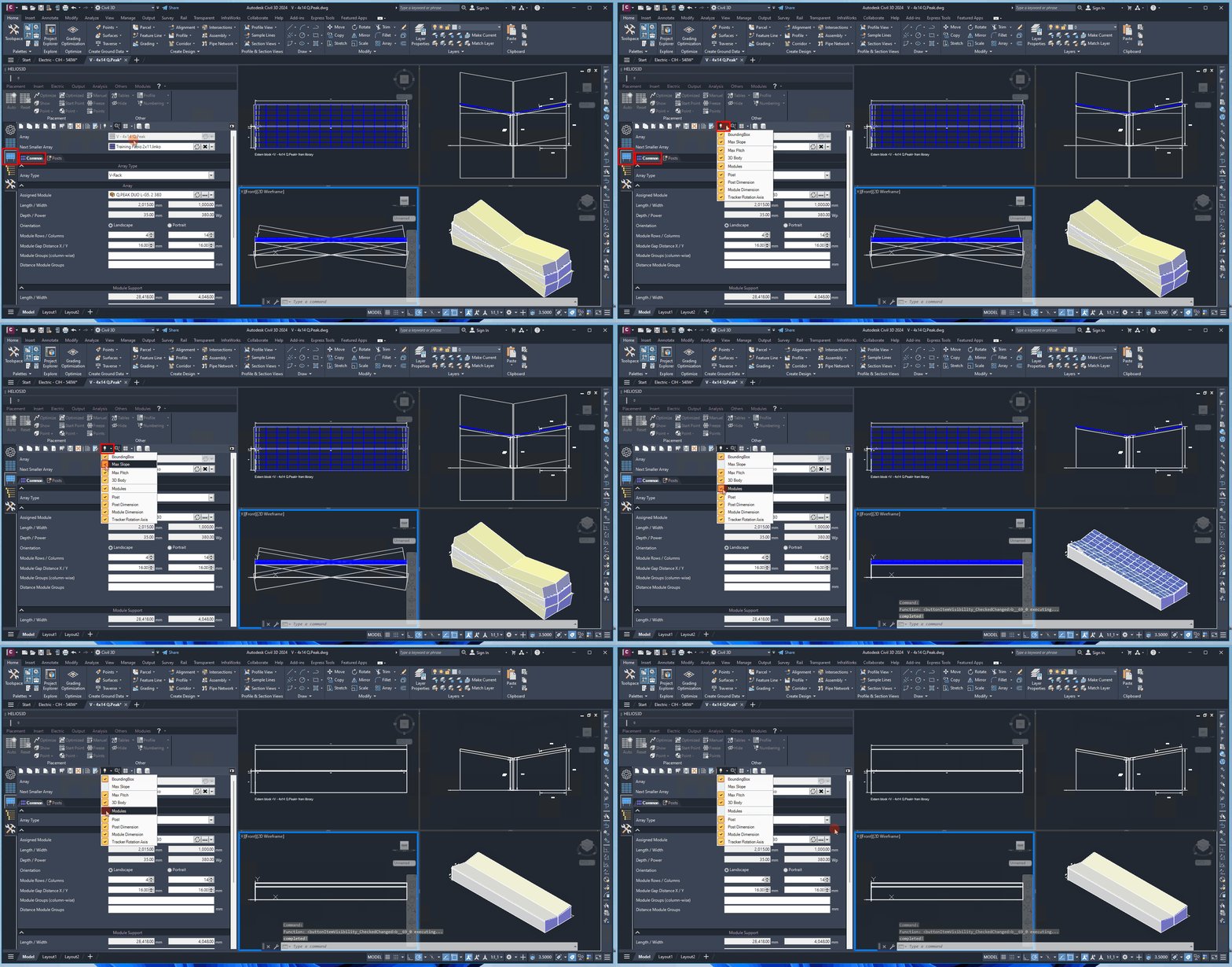
The button enables you to show or hide the drawing elements of an array definition. All components available for visibility management are illustrated in following Figure. Once you have made all necessary changes to the visibility settings, return to the drawing area with your mouse cursor to regenerate the drawing.
Use the visibility settings to control which drawing elements of the array definition are displayed. After changing the visibility settings, move the mouse cursor back into the drawing area so that the drawing can be regenerated and the updated visibility state becomes visible.
Troubleshooting
If the displayed array drawing does not change after adjusting visibility settings, move the mouse cursor back into the drawing area to trigger regeneration. If a detailed block representation does not behave like a parameter-based array drawing, check whether the geometry was inserted as a block and whether the fixed pitch limitation applies.