
Electric
It Contains all commands for placing electrical components and is activated whenever the user opens the „Electric“ module.
The Electric ribbon is the central command area for electrical design tasks in Helios 3D. It is used after the PV layout has been created and provides commands for automatic string placement, device assignment, cable routing, electrical loss calculation, numbering, rewiring, and visualization of electrical results. The ribbon supports both automatic and manual electrical workflows and helps users prepare the electrical layout for review, reporting, and further project documentation.
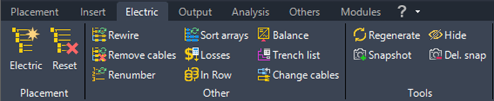
Command Group Placement
Before using the Electric commands, the project should contain a valid PV layout with placed arrays or module tables. Electrical components such as inverters, combiner boxes, transformers, cables, and related database articles must be defined consistently before reliable electrical placement or loss calculation can be performed. If required data is missing, some commands may not produce complete results or may display warnings about incomplete articles.
Automatic electric placement

Starts the automatic placement of strings and devices with the parameters set below, including cable routing and electrical losses.
After a placement is completed, only hatches are displayed as the result. Options for displaying the actual cables or the connections between modules and a collecting device can be found on the other tabs of the Electric module.
The automatic electric placement creates the logical electrical structure for the selected placement sets. Depending on the project setup, this may include string grouping, assignment to electrical devices, cable routing, and loss-related information. The visible result may differ from the stored electrical structure: hatches or markers can represent the placement result, while detailed cables and connections can be displayed separately through the Electric module.
Reset

Reset / delete the string placement for the selected selection sets.
Use Reset carefully, because it removes the existing string placement for the selected selection sets. This can affect subsequent electrical calculations, device assignments, cable routing, numbering, and reports that depend on the electrical design. If only the visible cable display should be removed, use the temporary object tools instead of deleting the electrical placement.
Command Group Other
Rewire string placement

Rewires the placement and recalculates the connections for any electrical device that has been moved.
For unmoved devices there will be no change, except the whole cable connections were removed.
Rewire is useful when electrical devices have been moved after an automatic or manual electrical placement. The command recalculates the affected cable connections while keeping unchanged devices stable where possible. Use this command after modifying device positions, changing cable trenches, or removing cable connections while keeping the assignments.
Sort Arrays by Cable Trench
This function reorganizes rows with tables of different sizes, moving smaller tables closer to the cable trench. After activating the function, you will be prompted to select a single cable trench.
If there are multiple trenches within one field, you will need to run this function multiple times. Rows that do not intersect with the selected cable trench will remain unchanged.
Balance inverter input use

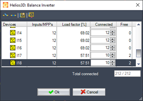
Opens the dialogue with a list of inverters for the selection set. There you can change the use of inputs.
The automatic placement always uses inverters to their maximum capacity, so only an overload can result in free input. If the last inverter in a placement has fewer strings remaining to be connected, only that device will have free inputs or MPPTs. This function allows for quick balancing by reorganizing the connection numbers.
Disconnect

For each selected device, one string or MPPT will be disconnected. The disconnected objects (strings/MPPTs) will remain unconnected until the user manually reconnects them.
Connect

For each selected device, one input object (either an input string or MPPT) is assigned from the pool of temporarily unconnected objects.
Connect all free inputs

Connect unconnected objects to the selected device until all of its input slots are filled.
This process requires selecting a single inverter or combiner box entry, allowing connections to be added until the device reaches full capacity or no unconnected objects are left.
Balance inputs

„The inputs of the selected device (only one device can be selected at a time) are filled with connections from previously used devices until the number of inputs matches the number used by the previous device. For each former device, one string or a complete MPPT is disconnected to provide connections for the current device. This process ensures that multiple former devices are uniformly modified.
For example: If an inverter with 4 open inputs across 2 MPPTs is selected, one entry from the former inverter will be disconnected to fill the connections for the current inverter.“
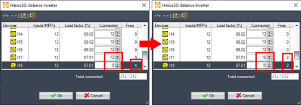
For inverters without MPPTs, one input from each of the former inverters will be disconnected to provide the necessary connections for the selected device.
Balancing uses inverter inputs now
From now on, balancing distributes the number of unused inputs evenly across a matching number of inverters, rather than balancing the number of unused MPPTs.
This approach ensures that no MPPT is left completely unused while others have all their inputs occupied.
In the example below, the automatic placement result is marked in blue, while the suggested balancing result is highlighted in orange.
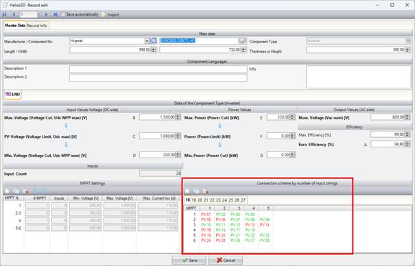
Connection schemes for string inverters added
String inverters can be configured with specific input usage schemes based on the number of connected strings.
In the image below, the scheme section illustrates a configuration where the red-marked inputs are blocked when 18 strings are connected.
Currently, connection schemes are only applied during the balancing process. Automatic placement halts when the last inverter in a selection set is not fully utilized and prompts the user with the balancing dialogue.
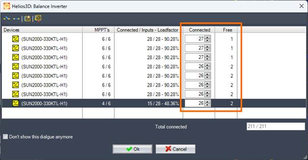
The final balancing settings define the connection scheme and determine which inputs are blocked for string connections.
In the image below, inverters are shown with 27 or 26 connected strings.
In complex scenarios—such as when strings from different module rows need to connect to different MPPTs or when varying string lengths are used—this may result in additional inverters being inserted. The decision to override placement rules must be made manually by the user.
To support this, the manual electrical design has been enhanced to display the inputs for each MPPT, allowing for direct assignment. Additionally, strings can now be reassigned to different inputs across MPPTs or even inverters using drag-and-drop.
Extended Commands in the Balancing Dialog
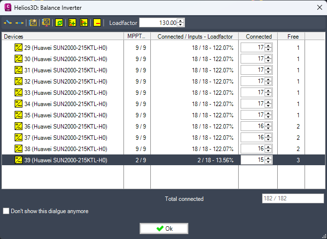
The balancing dialog for distributing strings to target devices provides additional commands for replacing, inserting and removing devices.
The dialog also allows the inverter load factor to be changed during the manual balancing workflow.
Exchange Device

Exchange Device replaces the currently selected device with another component from the database.
The replacement component must be suitable for the current electrical hierarchy. An alternative string inverter or DC combiner box must already be assigned to the device hierarchy before it can be used in this workflow.
Select the device that must be replaced and choose a compatible alternative from the available database components.
After the exchange, verify the number of inputs, MPPT configuration, connected strings and load factor.
Exchange Device – Limitation
Replacing a string inverter with a device that has fewer inputs or fewer MPPTs may fail because the existing string connections cannot be transferred according to the internal connection rules.
If the direct exchange fails:
- insert a new device;
- assign or distribute the required strings;
- check the input and MPPT allocation;
- remove the previous standard device after the new assignment has been verified.
Do not remove the original device before confirming that all required strings can be connected to the replacement.
Insert at End of List

Insert at End of List creates a new device at the end of the device list.
The new device uses the same component type as the device currently selected in the list.
Use this command when another matching target device is required after the existing devices.
Insert at Current Position

Insert at Current Position creates a new device at the currently selected position in the list.
The new device uses the same component type as the selected device.
The inserted device changes the list sequence. Review the distribution of strings before confirming the balancing result.
Remove Device

Remove Device removes all selected devices from the balancing list.
Before removing a device, check whether strings are still connected or assigned to it. Make sure that the remaining devices provide enough available inputs and MPPTs for the required connections.
Removing several selected devices can affect a large part of the string distribution.
Load Factor
The Load factor field changes the permitted inverter load factor for the current balancing workflow.

The selected value is stored in the electrical settings.
When manual changes are executed, Helios 3D uses the new load-factor limit for the string-to-inverter distribution.
Effect of Changing the Load Factor
If automatic string-to-inverter distribution previously skipped inputs because of the configured load factor, the new limit is considered when the manual changes are applied.
A manually adjusted string-to-inverter assignment may be modified again if it exceeds the new load limit.
Increasing or decreasing the load factor can therefore affect assignments that were already adjusted in the dialog.
Before confirming the changes, review:
- the load factor of each inverter;
- the number of connected strings;
- the available inputs;
- the available MPPTs;
- the total number of connected strings;
- warnings or assignments that exceed the new limit.
Checking Manual Changes
Before closing the balancing dialog, verify that:
- all required strings are connected;
- no unintended device was exchanged;
- newly inserted devices use the correct component type;
- removed devices are no longer required;
- the number of connected strings matches the expected total;
- no inverter exceeds the permitted load factor;
- the input and MPPT assignments are valid;
- manual changes were not unexpectedly modified by the new load limit.
Confirm the dialog only after the resulting string-to-device distribution has been reviewed.
Remove cable connections but keep assignments

Removes all connections between strings and devices, while retaining the general assignment between devices. Later, the wiring can be easily completed using the „Rewire“ command.
This option can also be used to replace or modify the cable trenches in use.
Calculate cable losses

Calculates the losses for the existing cable layout. In case any article contains missing information for loss calculation, a message will show a list of incomplete articles.
Cable loss calculation depends on complete and correct cable and component data. If article data such as cable type, cross-section, electrical parameters, or device information is incomplete, Helios 3D may not be able to calculate all losses. In this case, review the listed articles in the database and complete the missing information before recalculating the cable losses.
Cable trench detail list

Displays a list of all selected cable trenches, or all cable trenches in general, along with detailed information (such as contained cables, etc.).
The list can be printed as a report in the subsequent dialog.
Renumber electrical design

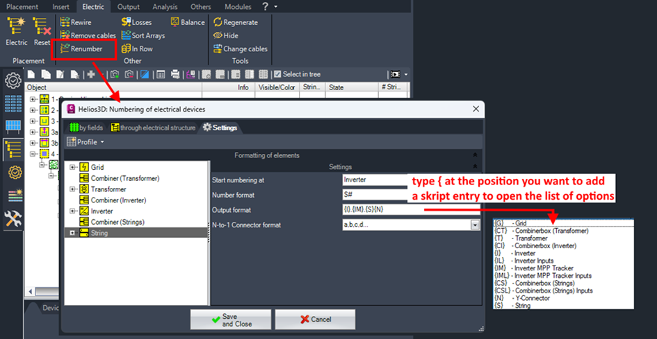
Opens the dialogue for creating and applying a numbering scheme for the strings and electrical devices. The renumbering can be executed „by fields“ and selection sets or „through electrical structure“ which includes the exact assignment to target device input numbers.
Renumbering should be performed after the electrical structure is stable. If strings, devices, MPPT assignments, cable trenches, or manual connections are changed later, the numbering may need to be repeated. Choose the numbering method according to the planning goal: numbering by fields is useful for layout-based documentation, while numbering through the electrical structure reflects the actual device and input assignments.
Page „Settings“
- Start numbering at
Allows you to set global numbers or choose a parent device, where the numbering will restart from 1 for the selected entry. - Number format
Text that surrounds the numbers in the output format. The „#“ symbol sets the position of the number. To ensure a fixed number of digits, multiple „#“ symbols will add leading zeros to smaller numbers.
„##“ formats the number for the first device as 01. - Output format
Defines the output format for the string or device using a list of macros, which are always surrounded by { }. Type { to display a list of available macros. - N-to-1 Connector format
When Y-connectors or multi-connectors are used, the string number is extended according to the selected format.
Pages “by fields” and “though electrical structure”
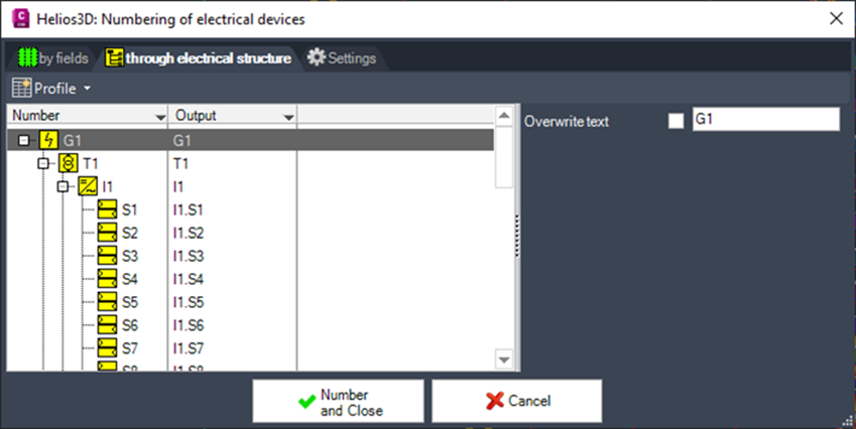
With the set format, string and device numbers can be generated by fields (row and array positions) or through the electrical structure (which also includes manual device connections).
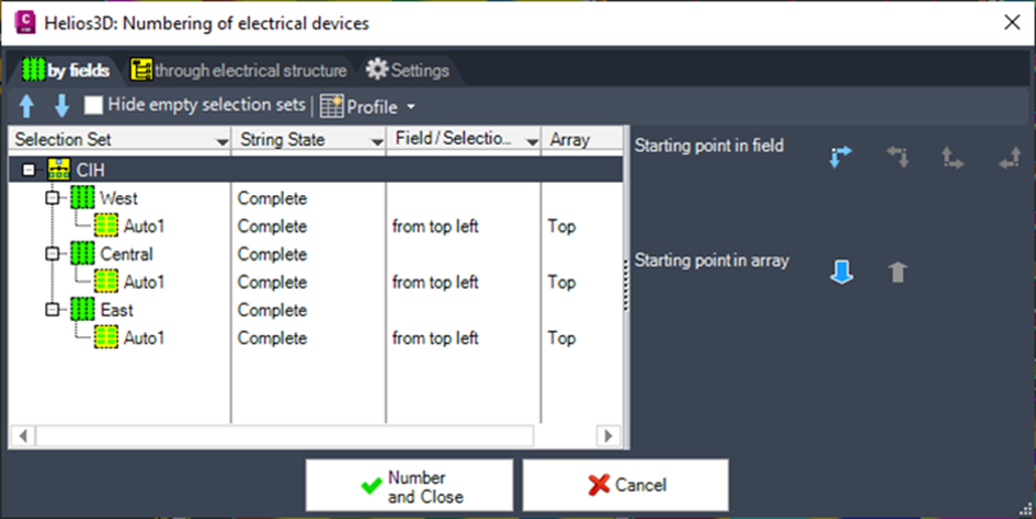
Numbering by field allows you to set the order of fields and selection sets. Within the selection sets, the internal order of the numbers is determined by the arrow buttons on the right under „Starting point in field“ and „Starting point in array.“
The numbering through the electrical hierarchy uses the exact input connection points, including manual assignments to a specific input or MPPT.
Change Text for Electrical Devices
The Change Text for Electrical Devices command changes the text label of a selected electrical device directly in the drawing.
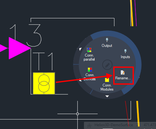
Use this command when the displayed text of an individual device must be changed without repeating the complete electrical numbering process.
The command changes the text of the selected device only. The new text is not automatically transferred to connected devices or to labels that contain information from the renamed device.
Selecting an Electrical Device
Start the Change Text for Electrical Devices command and select the electrical device whose displayed text should be changed.
Make sure that the correct device is selected. In drawings containing several devices at similar positions, use the electrical structure to verify the device before applying the change.
Only change device labels after the electrical structure and device assignments have been checked.
Changing the Device Text
Enter the new text for the selected device and confirm the change.
The new text replaces the current label of the selected device in the drawing.
Use a label that follows the naming and numbering convention of the project. The text should remain unique and should allow the device to be clearly identified in the drawing and electrical documentation.
After confirming the change, check the position and readability of the new label.
Effect on Connected Devices
Changing the text of an electrical device does not automatically update the labels of connected devices.
The command affects only the selected device label. Text references that have already been generated for connected strings, collectors, inverters, transformers or other electrical objects retain their existing values.
If connected labels must also contain the new device text, they must be checked and updated separately.
Example: Transformer and String Labels
If the text label of a transformer is changed, the new transformer name is not automatically displayed in the labels of the connected strings.
This also applies when the transformer number is configured as part of the string-label format. Existing string labels retain the transformer-related value that was present when the labels were generated.
For example:
Original transformer label: TR-01
Generated string label: F01-TR-01-S01

Changed transformer label: TR-A
Existing string label: F01-TR-01-S01
Changing the transformer label to TR-A does not automatically change the existing string label to F01-TR-A-S01.
If the string labels must contain the new transformer text, update or regenerate the affected labels using the appropriate electrical numbering function.
When to Use the Command
Use Change Text for Electrical Devices when:
- the label of an individual device must be corrected;
- a temporary device designation must be replaced;
- a project-specific device name is required;
- a drawing label must be adjusted without renumbering the complete electrical structure;
- a spelling error in a device label must be corrected.
Use the electrical numbering command instead when several devices or connected labels must be updated according to a consistent numbering scheme.
Checking the Result
After changing the device text, verify that:
- the correct electrical device was changed;
- the new text follows the project naming convention;
- the new device label is unique;
- the label is readable;
- the label does not overlap the device symbol, cables or other annotations;
- the electrical structure still identifies the intended device;
- connected labels do not contain an unintended outdated value;
- affected string or device labels are regenerated if necessary.
Also check reports and exports that may contain device-related labels. Existing output files are not automatically updated when a label is changed in the drawing.
Important Limitations
Important:
The command does not propagate the new text through the electrical structure.
Changing the label of a parent device does not automatically update connected or subordinate objects.
In particular:
- changing a transformer label does not automatically update connected string labels;
- changing an inverter label does not automatically update labels of connected strings;
- changing a collector label does not automatically update labels of connected devices;
- previously generated reports or export files are not updated;
- existing labels containing the old device text may need to be regenerated.
Before changing a label, determine whether the device text is used in other labels, reports or exports. After applying the change, review all affected electrical documentation.
Connect transformers in row or to grid

Connects a transformer in a row. The function prompts for the transformer to reconnect, and then asks for the new target transformer via the AutoCAD command line.
Change cables in layout
Opens the dialog for manually changing assigned cables, such as to avoid excessive losses. This dialog displays the current state of the electrical layout along with a preview. In the preview, you can replace cables with a different cross-section to resolve power loss issues. Once all issues are addressed, you can apply or discard the changes.
The following figure shows an example with losses for the central inverter. The maximum allowed loss is set to 1% (this can be adjusted by clicking the sun symbol on the Helios 3D palette under „Properties“).
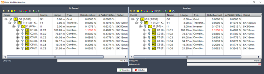
The toolbar commands can be used to display cables or connections between objects. These commands are described for the electrical structure tree, as most of them are the same, except for the last two.

Reset

Resets any actions that have not been applied in this dialog.
Exchange Cables

Opens the dialog for exchanging the cables for the current selection and all devices on its input side. The following figure shows the exchange of all combiner box output cables.

After the cable exchange, the power loss issue is resolved, and the Analysis Mode displays the following.
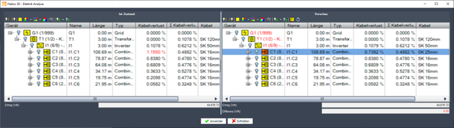
The devices that were changed appear in orange, as shown here.

The preview allows users to test cable changes before overwriting the current layout. Use this workflow to resolve excessive power loss, compare cable cross-sections, and verify whether the modified cable selection meets the project requirements. Only apply the changes when the previewed result has been checked and accepted.
To permanently save the new results, you need to click

which will overwrite the original electrical layout.
Command Group Tools
The tools include function calls related to transient objects, which are temporarily displayed and neither printable nor visible if the drawing is opened without the Helios 3D extension.
Temporary Electric objects are mainly used for visualization and checking. They can show selection set colors, cable runs, connection markers, hatches, or other temporary graphics generated by the Electric module. These objects are not a replacement for the stored electrical structure. If the drawing must be shared or documented with visible electrical graphics, create a snapshot to convert the current temporary display into permanent AutoCAD objects.
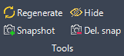
Here, any temporary drawing objects from the Electric module (such as hatches, triangles, and displayed cable runs) can be regenerated.
Regenerating temporary objects

Redraw all temporary objects as selection set colors, cables or connection markers.
Remove all temporary objects

Removes all temporary cables and colors of the electric module from the drawing..
Create snapshot

A snapshot converts all temporary objects, which represent currently displayed cables and hatches (array markers), into permanent 3D AutoCAD objects on the layer „H3D_Snapshots.“ These objects behave like any other regular object, allowing you to select them.
Remove snapshots

Deletes all objects on the „H3D_Snapshot“ layer, which is exclusively reserved for snapshots.