
Calculation of Cable Lengths
Cable length calculation depends on the cable section and on how the connection is routed through the electrical structure. The article distinguishes between single-wire sections near the module strings and twin-wire sections after the combiner box or string inverter.
Please note that there are two basic cable sections. In the first section, Helios 3D uses two single wires—one for each path/direction. In the second section, a twin wire is used for both directions. These two sections are clearly separated by the combiner box or string inverter. The distinction between the sections is illustrated in the drawing for easier understanding.
Single Wire / Twin Wire
For the wiring between the module strings and the combiner box (or string inverter), Helios 3D uses single wires for each direction. One wire carries the positive („+“) connection from the module string to the back end of the table and to the combiner box connection point, while the other wire carries the negative („-„) connection from the module string.
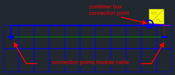
From the combiner box or string inverter (target device), you can configure the device hierarchy to specify how many physical cables are used for the outgoing phases. When the target device is placed on a table that isn’t next to the cable trench, the cable is routed back to the cable duct on the table.
If the table is the first one next to the trench, the value set on the Settings page inside the Electric module is used to determine the cable distance between the device output and the ground. The following figure illustrates this distance. The calculation for the cable continues from the closest point on the ground to the trench, along the center axis of the table.
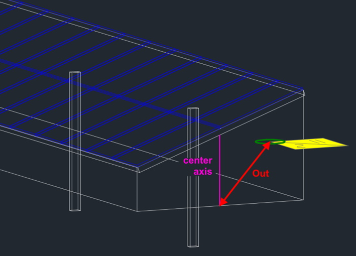
From the ground point, the cable is routed vertically to the trench depth and then to the cable trench.
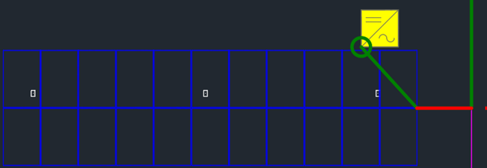
At the device areUse this tab to verify whether cable connections, cable visibility, connected modules, device relationships, and summarized cable lengths are displayed as expected. If a cable or module group is not visible, first check the selected entry in the electrical structure tree and the corresponding show/hide options.a, the cable is routed vertically from the trench up to the ground